Inverter-integrated motor for an automotive vehicle

a technology of inverter-integrated motors and automotive vehicles, which is applied in the direction of piston pumps, domestic cooling devices, lighting and heating apparatus, etc., can solve the problems of increasing the capacity or volume of engine room devices associated with the engine, and affecting the efficiency of the engine. , to achieve the effect of facilitating the removal of power terminals and being easy to manufactur

Inactive Publication Date: 2006-03-30
DENSO CORP
View PDF27 Cites 74 Cited by
  • Summary
  • Abstract
  • Description
  • Claims
  • Application Information

AI Technical Summary

Benefits of technology

[0012] To solve the above-described problems, the present invention has an object to provide an inverter-integrated motor for an automotive vehicle capable of assuring anti-vibration properties and realizing the downsizing of the inverter section.

Problems solved by technology

It is hence difficult to replace the conventional belt-driven compressor by the above-described inverter-integrated motor-driven compressor.
The processes and the costs will increase.
Furthermore, the engine room capacity or volume available for the devices associated with the engine tends to decrease.
It was however difficult to cool the inverter section when it is placed adjacent to the motor section.
However, it is not easy to effectively guide or introduce the cooling air or the low-temperature coolant gas toward the inverter section in the axial direction via a branched or bent route or passage of flow.
This will necessarily increase the circumferential and axial size of the apparatus.
The wiring work will become complicated.
In this respect, there is a limit in realizing a high-density wiring, i.e., in realizing the downsizing of the inverter section.

Method used


Image

  • Inverter-integrated motor for an automotive vehicle
  • Inverter-integrated motor for an automotive vehicle
  • Inverter-integrated motor for an automotive vehicle

Examples


first embodiment

[0120] An inverter-integrated motor-driven compressor of a refrigerating cycle for an automotive vehicle in accordance with a first embodiment of the present invention will be explained with reference to accompanied drawings, although some of constituent members and lines are omitted.

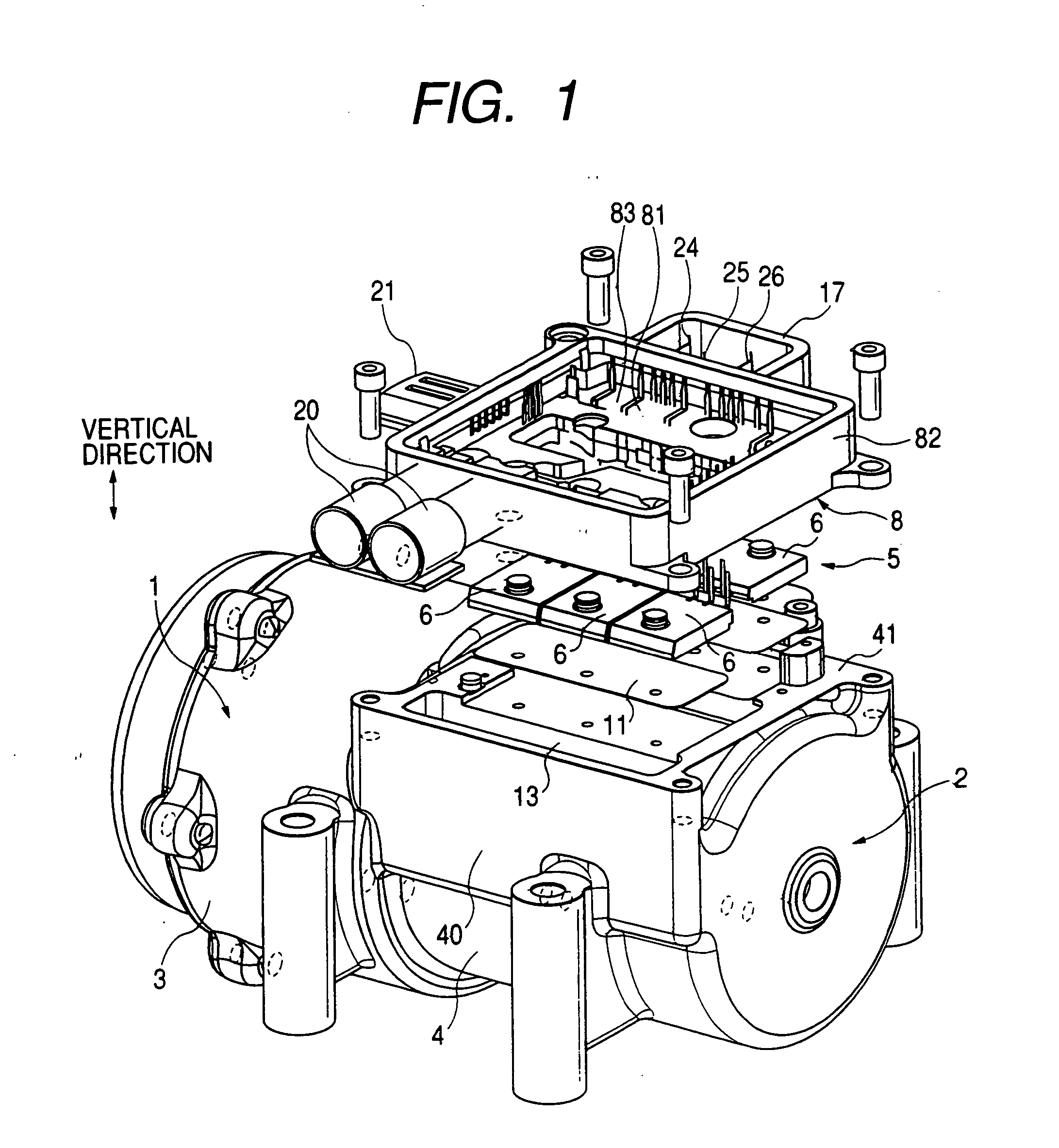
[0121]FIG. 1 is an exploded perspective view showing the inverter-integrated motor-driven compressor in accordance with the first embodiment of the present invention.

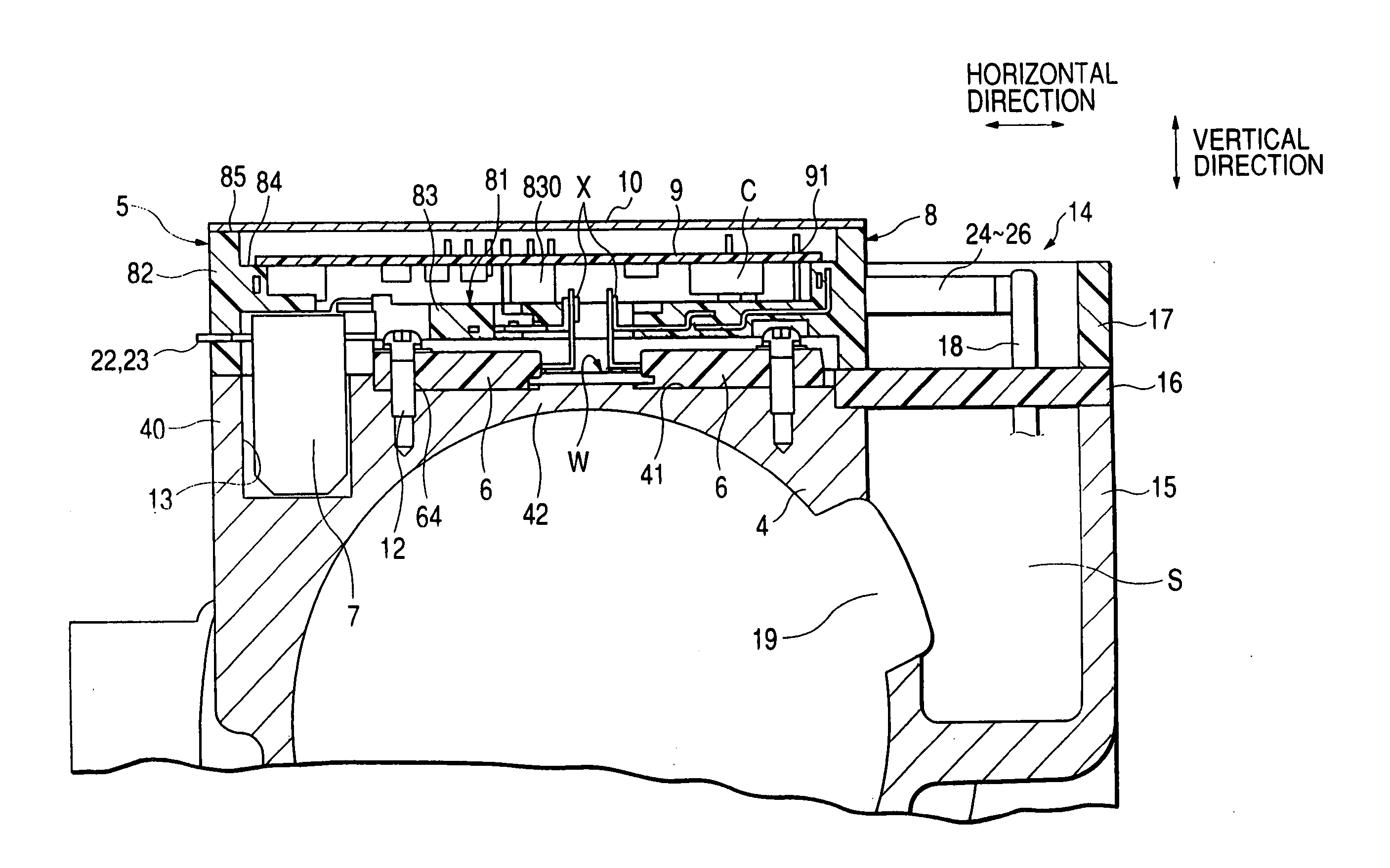
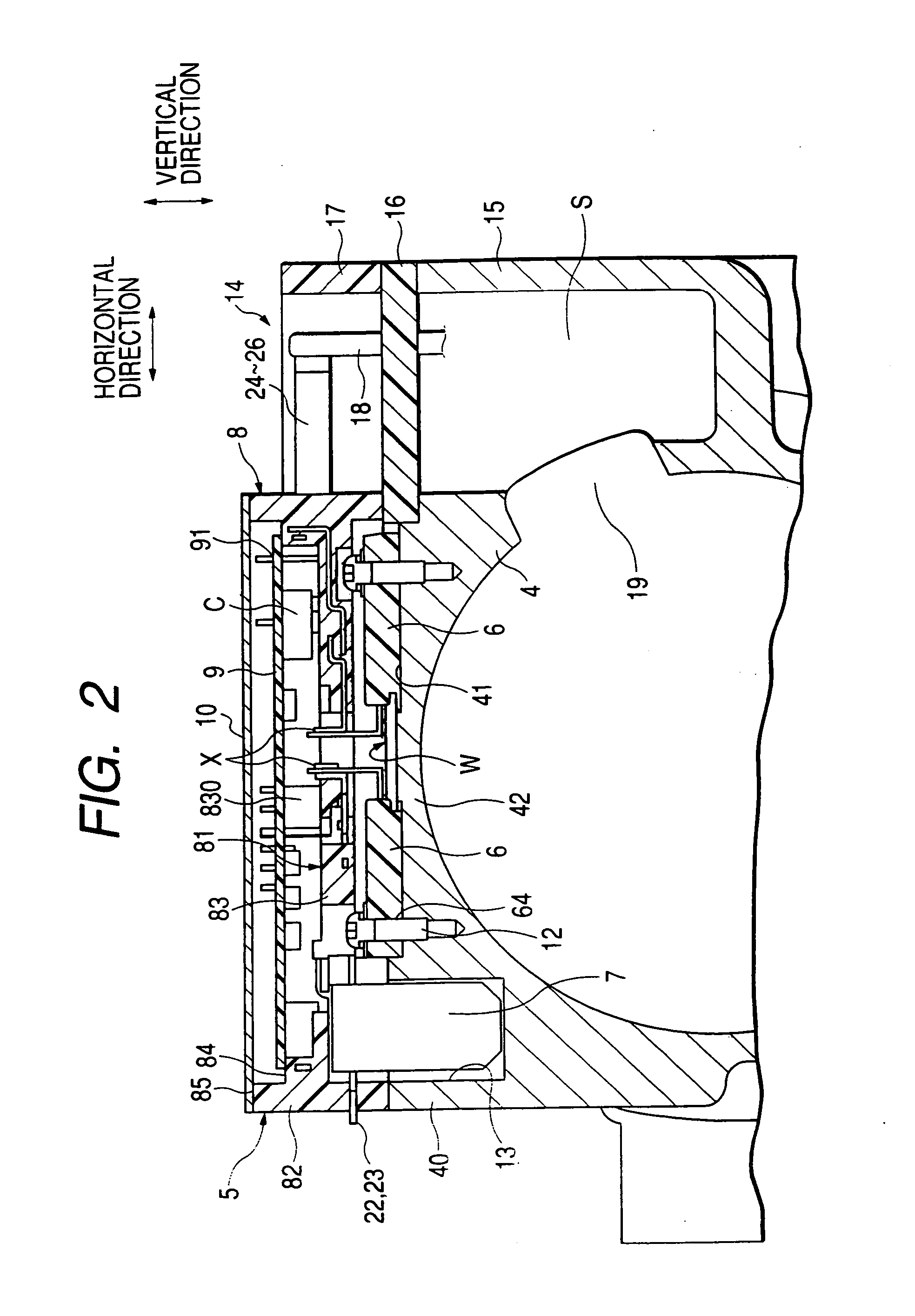
[0122]FIG. 2 is a cross-sectional view showing an inverter circuit section of the inverter-integrated motor-driven compressor shown in FIG. 1, taken along the radial direction of the compressor. FIG. 2 shows the inverter circuit attached to a housing of the motor driven compressor. FIG. 2 does not show a refrigerating circuit as it is conventionally well known.

[0123]FIG. 3 is an exploded perspective view showing a plurality of power MOS transistor modules 6 mounted on a mounting base surface 41 of a motor housing 4.

[0124]FIG. 4 is a pla...

second embodiment

[0183] Hereinafter, an inverter-integrated motor-driven compressor for an automotive vehicle in accordance with a second embodiment of the present invention will be explained with reference to FIGS. 7 to 10.

[0184]FIG. 7 is a perspective view showing the inverter-integrated motor-driven compressor in accordance with the second embodiment. FIG. 8 is a rear view of the inverter-integrated motor-driven compressor shown in FIG. 7. FIG. 9 is an exploded perspective view of the inverter-integrated motor-driven compressor shown in FIG. 7.

[0185] (Overall Arrangement)

[0186] A compressor section c constitutes part of a refrigerating cycle apparatus for an automotive air-conditioning system. A compressor housing 201 accommodates a compressor section c. A cylindrical motor section m drives the compressor section c. A motor housing 202 accommodates the motor section m which is a three-phase synchronous motor. A motor control section 203, serving as an inverter circuit section of the present in...

third embodiment

[0210] An inverter-integrated motor-driven compressor of a refrigerating cycle for an automotive vehicle in accordance with a third embodiment of the present invention will be explained with reference to accompanied drawings, although some of constituent members and lines are omitted. FIG. 15 is an exploded perspective view showing the inverter-integrated motor-driven compressor in accordance with the third embodiment of the present invention. FIG. 16 is a perspective view showing a bus-bar assembly to be incorporated in the inverter-integrated motor-driven compressor in accordance with the third embodiment of the present invention. FIG. 17 is a perspective view showing bus bars to be molded in the bus-bar assembly shown in FIG. 16. FIG. 18 is an exploded perspective view showing the bus-bar assembly and power switching elements to be assembled together. FIG. 19 is a plan view showing the inverter-integrated motor-driven compressor shown in FIG. 15, although a cover plate and a prin...


PUM


Abstract

A bus-bar integrated plate and outer frame section, arranged into a double-deck structure and having numerous bus bars molded with a resin molding plate portion, is provided as a wiring for connecting power switching elements and a smoothing capacitor, fixed on an outer surface of a cylindrical wall of a motor housing, to a printed circuit board serving as a control circuit.

Description

[0001] This is a Division of application Ser. No. 10 / 422,958 filed Apr. 25, 2003. The entire disclosure of the prior application is hereby incorporated by reference herein in its entirety.BACKGROUND OF THE INVENTION [0002] 1. Field of the Invention [0003] The present invention relates to an inverter-integrated motor for an automotive vehicle, and more particularly relates to the improvement of its inverter section. [0004] 2. Description of the Background Art [0005] To maintain the condition of an air-conditioning system when an engine is temporarily stopped during a short period of time (e.g., during a so-called “idling stop” operation), it is conventionally known that a motor-driven compressor is preferably employed for a refrigerating cycle system of an automotive vehicle. Furthermore, it is conventionally known that a motor section of the motor-driven compressor is cooled by a low-pressure coolant gas. [0006] Furthermore, there is a conventional motor-driven compressor having an ...

Claims


Application Information

Patent Timeline
Patent Type & Authority Applications(United States)
IPC IPC(8): F25B49/00F25D23/12F25B1/00F01C21/10F04B35/04F04B39/12F04C29/00H02K5/22H02K11/04
CPCF01C21/10F04B35/04F04B39/121F04B2203/0204H02K11/0073F04C2240/808F25B2400/077H02K5/225F04C29/0085H02K11/33
Inventor FUNAHASHI, KENJIHAMADA, KENKAWATA, HIROYUKI
Owner DENSO CORP
Why Eureka
Try Eureka