
Gas flow control method in a blower based ventilation system

a technology of blower and ventilation system, which is applied in the direction of valves, mechanical equipment, operating means/releasing devices, etc., can solve the problems of system difficulty in correcting for sustained errors, failure of ventilators to adjust quickly and repeatedly to respond accordingly, and gas flow error as compared to the desired gas flow at the appropriate tim

Active Publication Date: 2006-03-30
TYCO HEALTHCARE GRP LP
View PDF19 Cites 35 Cited by
  • Summary
  • Abstract
  • Description
  • Claims
  • Application Information

AI Technical Summary

Benefits of technology

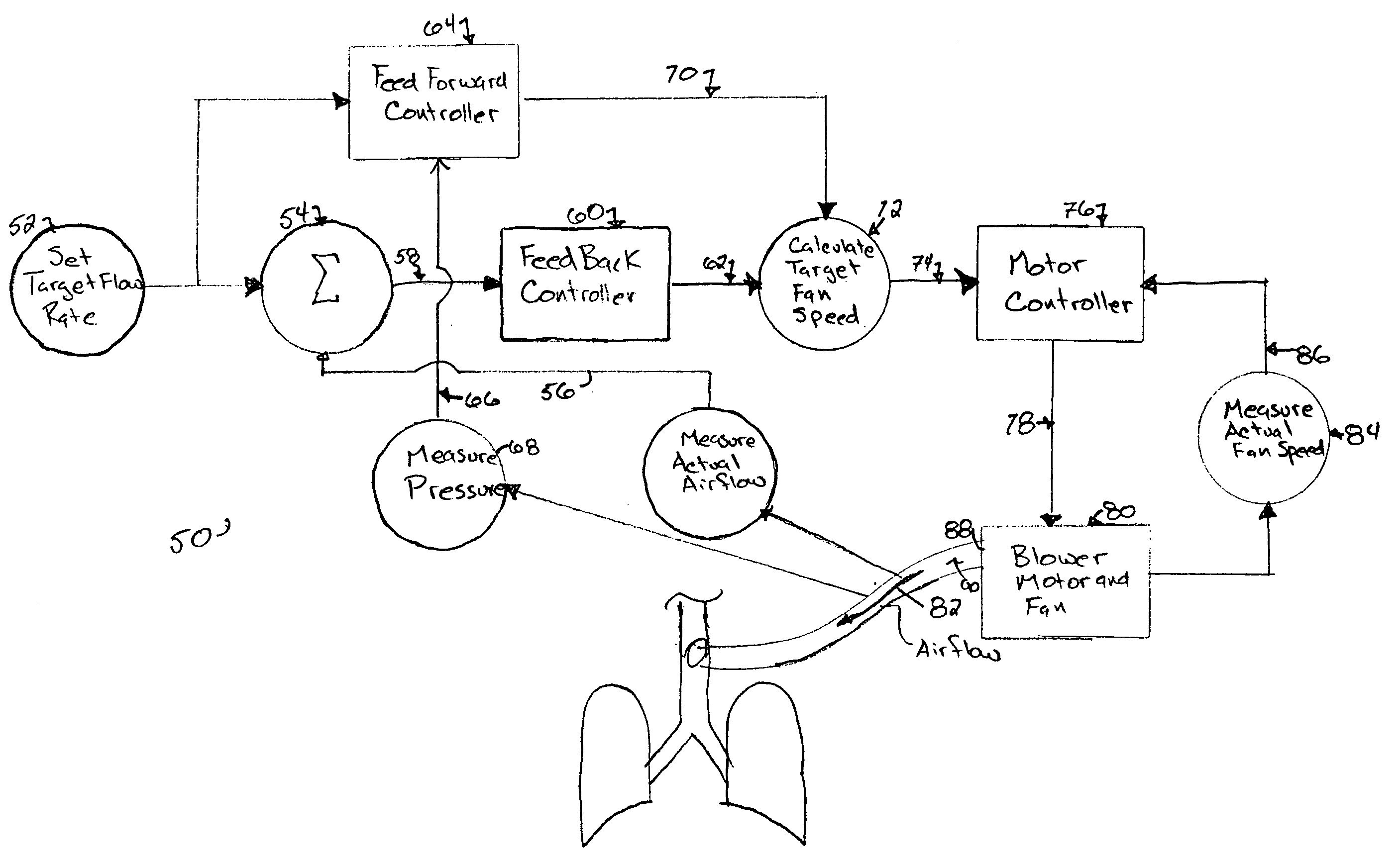
[0009] The present invention provides a system and method for providing a correction to a signal controlling a variable speed motor and blower within a medical ventilator system. The desired control system provides a feedforward controller which responds to the existing back pressure at the outlet of the blower. The feedforward controller accurately predicts the effect of the back pressure on the changes required in gas flow and required motor speed. In a preferred embodiment, the control system also includes a feedback controller which responds to the actual gas flow induced by the blower. In such an embodiment, the feedfoward controller and the feedback controller work in unison to establish a target gas flow.
[0011] The blower of the desired medical ventilator system is run by an electric motor which in turn is controlled by an electronic motor controller. The electronic motor controller provides a pulse width modulated (PWM) signal to the electric motor. By varying the pulse width of this signal, the electronic motor controller can vary the speed at which the motor runs. The electronic motor controller receives feedback from the motor which indicates actual motor speed. The electronic motor can thereby correct its PWM signal to correct the actual motor speed to the target motor speed. Of course, the target and actual motor speeds, correspond to the target and actual fan speeds respectively. Typically, the corresponding ratio between motor speed and fan speed is one to one. However, other corresponding ratios can be achieved.
[0016] To measure back pressure, a pressure transducer is included with the medical ventilator. This transducer may be placed anywhere downstream of the blower outlet, but is preferably located near the blower outlet. The pressure transducer is configured to transmit signals to the electronic feedforward controller. The transducer may be configured to continuously monitor the pressure or to take multiple measurements within a short time span.

Problems solved by technology

Errors in the delivery of gas flow as compared to the desired gas flow at the appropriate time can occur due to lag time between the onset of patient inspiratory effort and actual valve response time, regulator response, and valve gain variations.
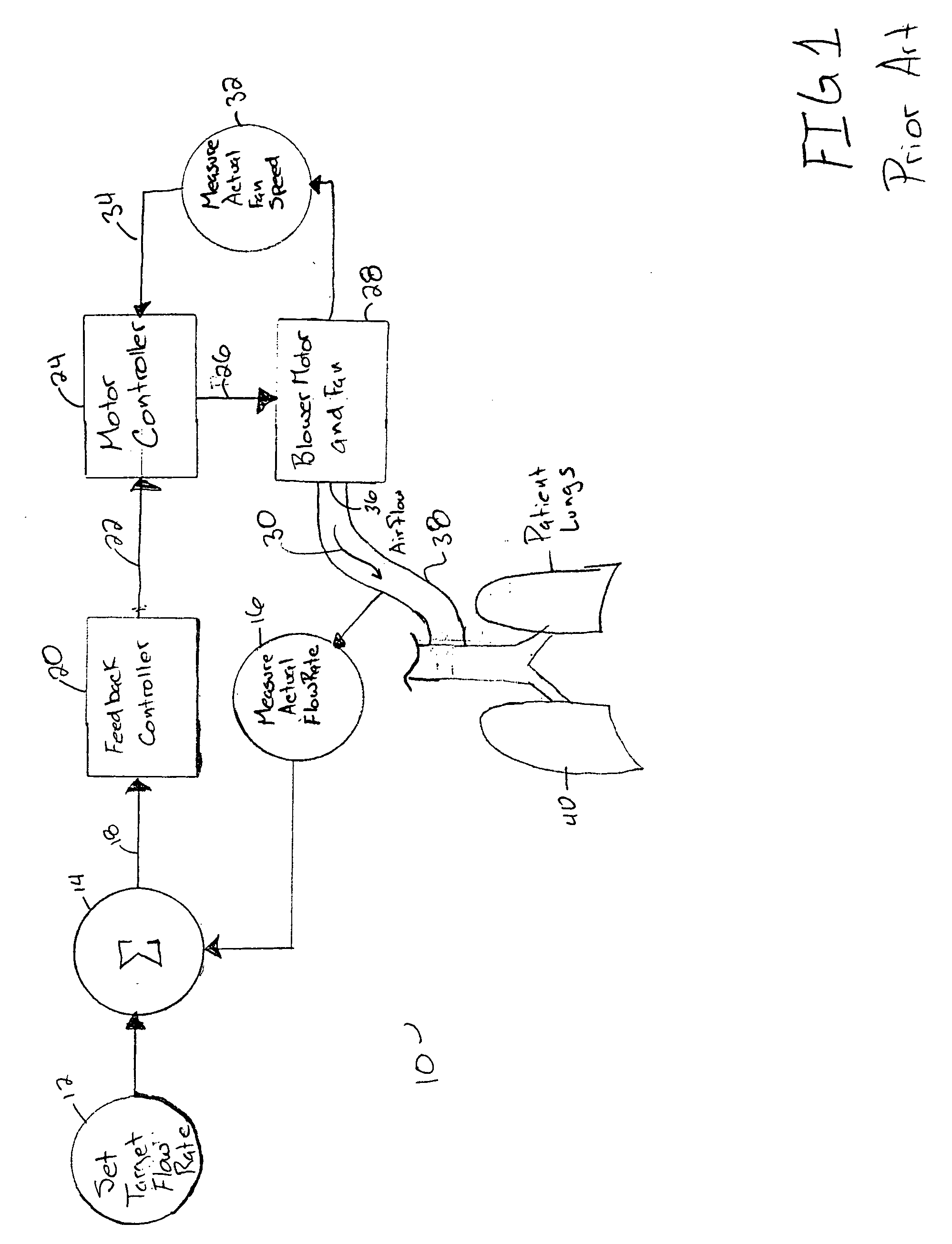
Although typical flow controllers may utilize a feedforward flow control gain component and various types of feedback error correction, such as proportional, integral, and derivative error feedback control, to compensate for real time disturbances that occur in the system, such systems frequently have difficulty in correcting for any sustained errors that occur periodically in the system.
Furthermore, a ventilator needs to make rapid and repeated adjustment to respond accordingly.
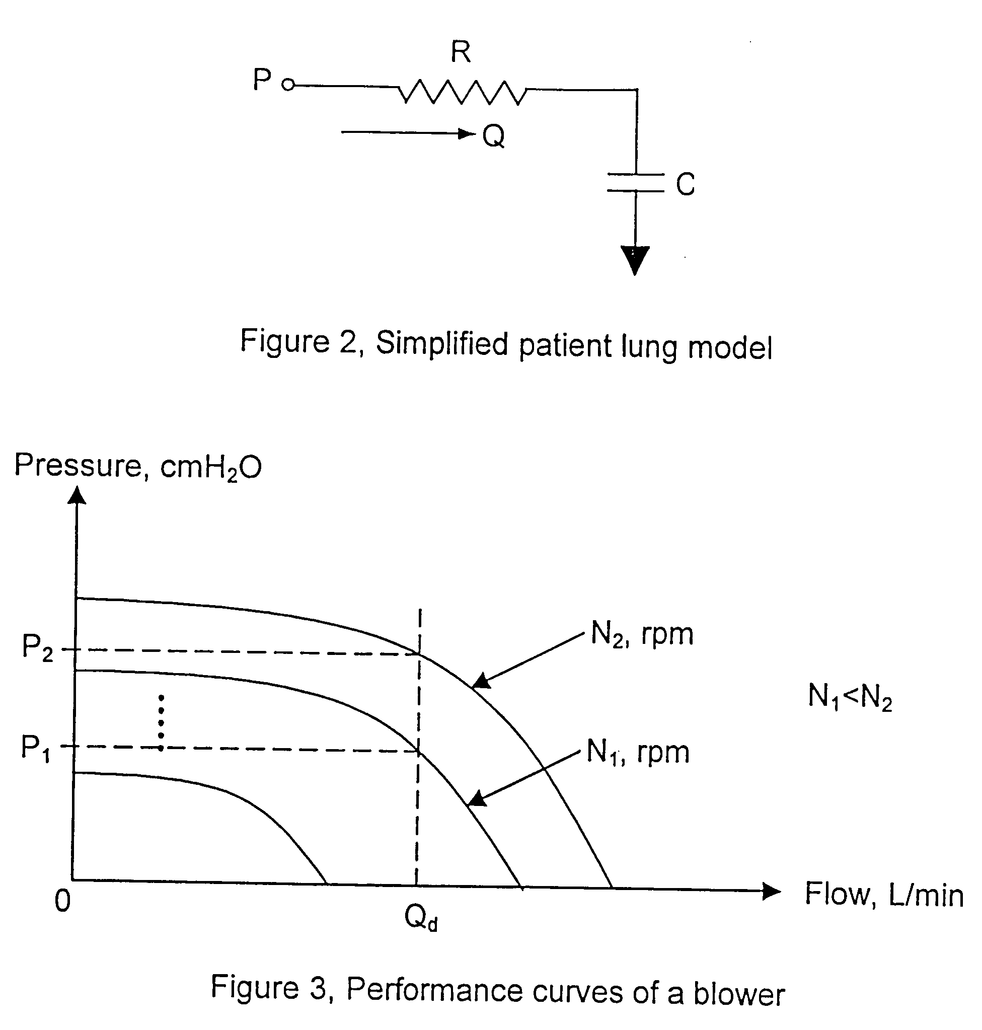
However, the static pressure at the blower outlet will affect the actual flow rate.
Unfortunately, in the environments experienced by medical ventilators, the static pressure may change significantly.
This may ultimately cause large deviations from the target flow rate.
Therefore, despite the ability to rapidly vary the actual flow rates, conventional blower-based ventilator systems have been unable to accurately maintain a target flow rate.
At worst, this method will produce an unstable control system which progressively deviates from the target flow rate.
At best, this method will produce a minimally stable control system which continuously oscillates about the target flow rate.
What has been needed and heretofore unavailable in a blower based medical ventilator in a control system that accurately compensates for environmental pressures to stably maintain a target flow rate.

Method used


Image

  • Gas flow control method in a blower based ventilation system
  • Gas flow control method in a blower based ventilation system
  • Gas flow control method in a blower based ventilation system

Examples


Embodiment Construction

[0029] The present invention is directed to a control system for a medical ventilator. The control system described herein is applied to a blower-based medical ventilator system. A blower-based system uses a blower, often configured as a fan, to generate a flow of respirator gas into the lungs of a patient. The flow of gas is generated by the blower and delivered to the patient through a tube. The gas flow rate in a blower based medical ventilators may be controlled by the fan-speed of the blower. Thus a variable speed fan is a desirable feature of such systems. Variable speed fans may be operated by an electric motor and an electronic motor controller which varies the electrical input signal to the electric motor to vary the speed of the motor and fan.

[0030] Modern medical ventilators are carefully controlled to meet the varying needs of the patient. One goal of modem ventilators is to respond to and encourage independent breathing efforts by the patient. Meeting this goal require...


PUM


Abstract

The invention is directed to a system and method for controlling the flow of gas from a medical ventilator into a patient's lungs. The control system provides for a non-linear feedforward controller to correct for disturbances caused by back pressure at the outlet of the blower of the medical ventilator. For this purpose, a pressure transducer is provided to measure the back pressure. Additionally, the invention allows for a feedback controller to correct for the differences between the rate of the actual gas flow and the targeted gas flow rate. For this purpose a flow rate transducer is provided. The control system may account for each of the gas flow rate error and the back pressure disturbance to provide for a quick and accurate adjustment to achieve the targeted gas flow rate.

Description

FIELD OF THE INVENTION [0001] This invention relates generally to the field of medical ventilators used to assist breathing in critical and non-critical patients. More particularly, this invention relates to a method and system for controlling the gas flow rate from a medical ventilator having a variable speed blower. BACKGROUND OF THE INVENTION [0002] Modern medical ventilators are designed to ventilate a patient's lungs with respiratory gas, and to thereby assist a patient when the patient's ability to breathe on his own is somehow impaired. As research has continued in the field of respiration therapy, a wide range of ventilation strategies have been developed. For example, pressure assisted ventilation is a strategy often available in patient ventilators and includes the supply of pressure assistance when the patient has already begun an inspiratory effort. With such a strategy, it is desirable to immediately increase the pressure after a breath is initiated in order to reach a ...

Claims


Application Information

Patent Timeline
Patent Type & Authority Applications(United States)
IPC IPC(8): A61M16/00A62B7/00
CPCA61M16/0057A61M2016/0039A61M16/0069A61M2205/3365A61M2205/3355A61M16/026
Inventor LI, KUN
Owner TYCO HEALTHCARE GRP LP
Learn More