
Drilling system and method for controlling equivalent circulating density during drilling of wellbores

a wellbore and circulation density technology, applied in the direction of survey, sealing/packing, borehole/well accessories, etc., can solve the problems of affecting the drilling operation, affecting the cleaning of the hole, and severely restricting the ability to clean the hole, so as to reduce the pressure of the bottomhole

Inactive Publication Date: 2006-03-30
BAKER HUGHES INC
View PDF52 Cites 98 Cited by
  • Summary
  • Abstract
  • Description
  • Claims
  • Application Information

AI Technical Summary

Benefits of technology

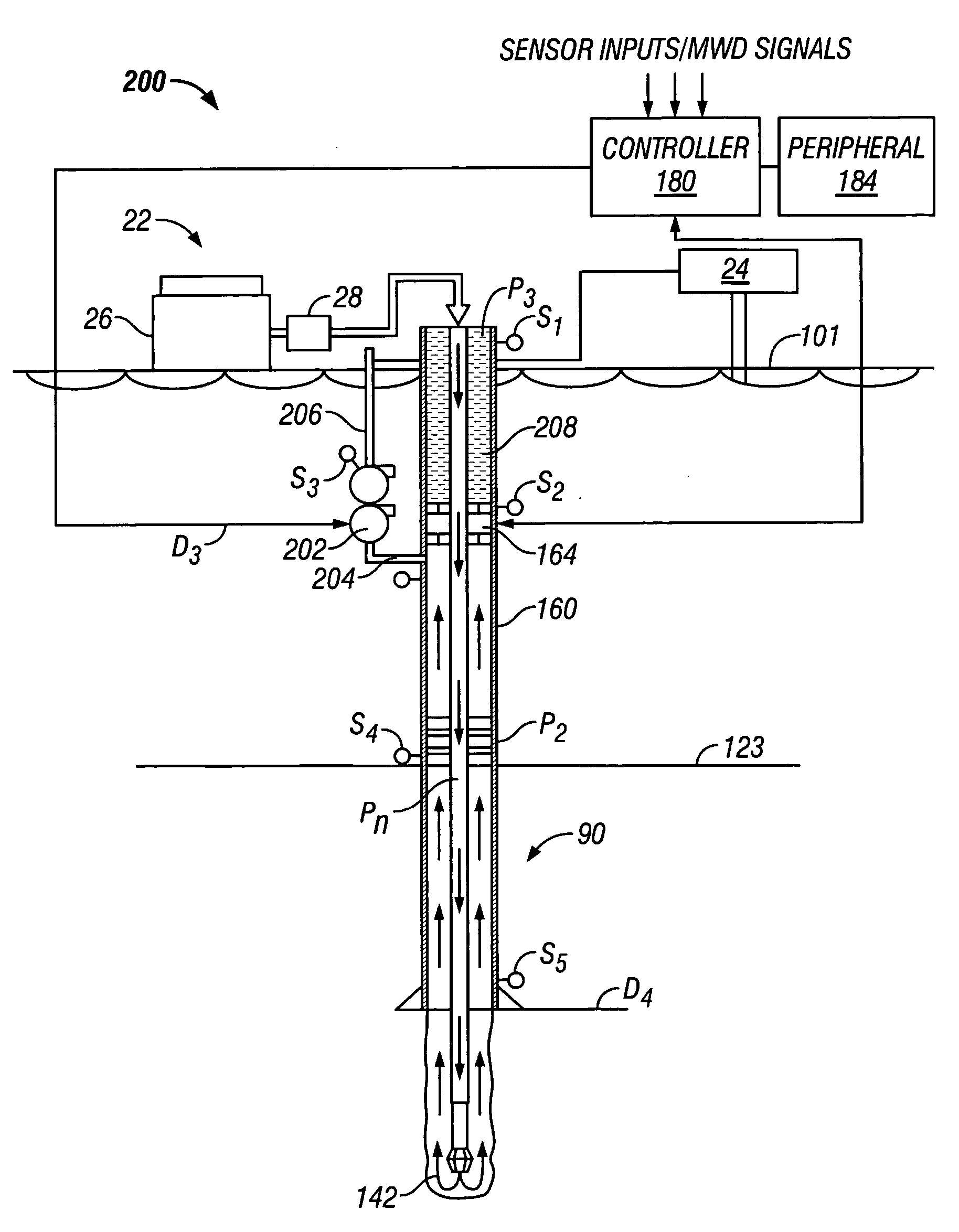
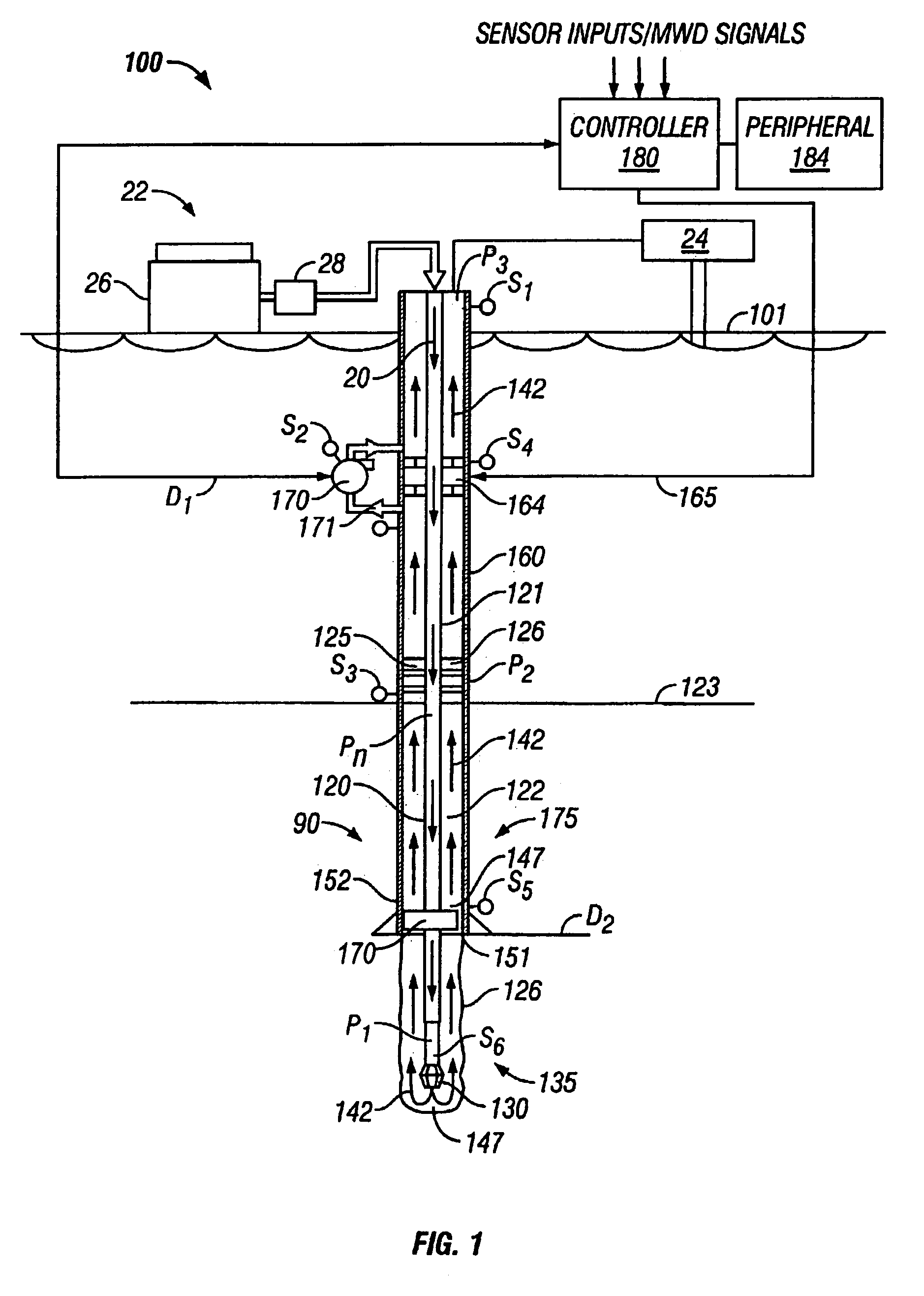
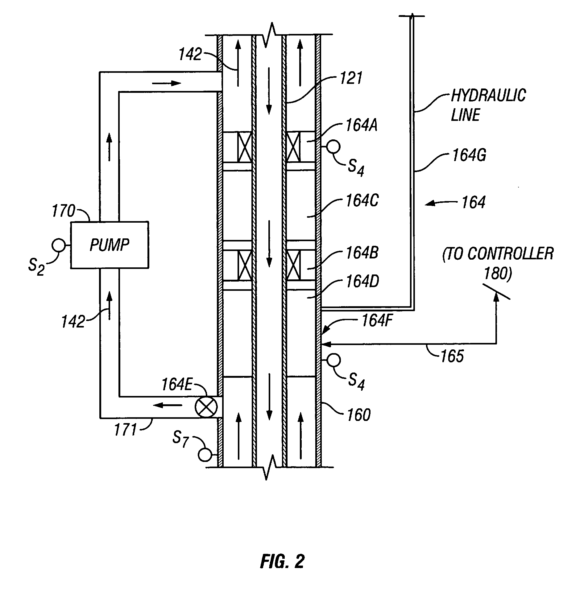
The present invention provides wellbore systems for performing subsea downhole wellbore operations, such as drilling. These systems include a rig at the sea level that moves a drill string into and out of the wellbore. A bottom hole assembly, carrying the drill bit, is attached to the bottom end of the tubing. A wellhead assembly or equipment at the sea bottom receives the bottom hole assembly and the tubing. A drilling fluid system supplies a drilling fluid into a fluid circuit that supports wellbore operations. The invention includes a flow restriction device in the riser that restricts the flow of returning fluid through the riser, a pump or turbine in the flow diverter line that controls the pressure differential and the equivalent circulating density, and a controller that maintains the pressure at a predetermined level or within a predetermined range. The invention is useful for achieving at-balance or under-balance drilling conditions.

Problems solved by technology

This pressure increase along the annulus of the well can negatively impact drilling operations by fracturing the formation at the shoe of the last casing.
In addition, the rate of circulation that can be achieved is also limited.
Due to this circulating pressure increase, the ability to clean the hole is severely restricted.
The level of complexity of the required subsea instrumentation and controls as well as the difficulty of deployment of the system has delayed the commercial application of the “dual gradient” system.

Method used


Image

  • Drilling system and method for controlling equivalent circulating density during drilling of wellbores
  • Drilling system and method for controlling equivalent circulating density during drilling of wellbores
  • Drilling system and method for controlling equivalent circulating density during drilling of wellbores

Examples


Embodiment Construction

[0023]FIG. 1 shows a schematic elevational view of a wellbore drilling system 100 for drilling a subsea or under water wellbore 90. The drilling system 100 includes a drilling platform 101, which may be a drill ship or another suitable surface work station such as a floating platform or a semi-submersible. A drilling ship or a floating rig is usually preferred for drilling deep water wellbores, such as wellbores drilled under several thousand feet of water. To drill a wellbore 90 under water, wellhead equipment 125 is deployed above the wellbore 90 at the sea bed or bottom 123. The wellhead equipment 125 includes a blow-outpreventer stack 126. A lubricator (not shown) with its associated flow control valves may be provided over the blow-out-preventer 126.

[0024] The subsea wellbore 90 is drilled by a drill bit 130 carried by a drill string 120, which includes a drilling assembly or a bottom hole assembly (“BHA”) 135 at the bottom of a suitable tubing 121, which may be a coiled tubin...


PUM


Abstract

A drilling system for drilling subsea wellbores includes a tubing-conveyed drill bit that passes through a subsea wellhead. Surface supplied drilling fluid flows through the tubing, discharges at the drill bit, returns to the wellhead through a wellbore annulus, and flows to the surface via a riser extending from the wellhead. A flow restriction device positioned in the riser restricts the flow of the returning fluid while an active fluid device controllably discharges fluid from a location below to just above the flow restriction device in the riser, thereby controlling bottomhole pressure and equivalent circulating density (“ECD”). Alternatively, the fluid is discharged into a separate return line thereby providing dual gradient drilling while controlling bottomhole pressure and ECD. A controller controls the energy and thus the speed of the pump in response to downhole measurement(s) to maintain the ECD at a predetermined value or within a predetermined range.

Description

CROSS-REFERENCES TO RELATED APPLICATIONS [0001] This application takes priority from Provisional U.S. Patent Applications Serial Nos. 60 / 303,959 and 60 / 304,160, filed on Jul. 9th, 2001 and Jul. 10th, 2001, respectively, and Provisional U.S. Patent Application Serial No. 60 / 323,797, filed on Sep. 20th, 2001. This application also takes priority from U.S. application Ser. No. 10 / 094,208, filed Mar. 8th, 2002 and Ser. No. 09 / 353,275, filed Jul. 14th, 1999, both of which claim priority from U.S. application Nos.: No. 60 / 108,601, filed Nov. 16th, 1998; No. 60 / 101,541, filed Sep. 23rd, 1998; No. 60 / 092,908, filed Jul. 15th, 1998; and No. 60 / 095,188, filed Aug. 3rd, 1998.BACKGROUND OF THE INVENTION [0002] 1. Field of the Invention [0003] This invention relates generally to oilfield wellbore drilling systems and more particularly to subsea drilling systems that control bottom hole pressure or equivalent circulating density during drilling of the wellbores. [0004] 2. Background of the Art [0...

Claims


Application Information

Patent Timeline
Patent Type & Authority Applications(United States)
IPC IPC(8): E21B7/12E21B21/00E21B21/08E21B33/076E21B43/12E21B47/00
CPCE21B7/12E21B21/001E21B47/0001E21B33/076E21B43/12E21B21/08E21B47/001E21B21/085
Inventor FONTANA, PETERWATKINS, LARRYARONSTAM, PETER
Owner BAKER HUGHES INC
Learn More