
Color picture tube

a color picture and tube technology, applied in the field of color picture tubes, can solve the problems of degrading color purity, affecting the shape of the tube, and the width of the black non-light-emitting layer cannot be kept sufficiently, so as to achieve satisfactory formability, less color purity degradation, and satisfactory visibility

Inactive Publication Date: 2006-03-30
MATSUSHITA TOSHIBA PICTURE DISPLAY CO LTD
View PDF30 Cites 2 Cited by
  • Summary
  • Abstract
  • Description
  • Claims
  • Application Information

AI Technical Summary

Benefits of technology

"The present invention provides a color picture tube with a shadow mask made of an inexpensive material that has good formability and uniform brightness. The tube has a phosphor screen and a shadow mask with a perforated region and a radius of curvature of the panel. The distance between the panel and the electron beam passage apertures is specified. The shadow mask is made of iron or a material containing 95% or more of iron. The technical effects of the invention are improved visibility, reduced color purity degradation due to doming, and excellent uniformity of brightness."

Problems solved by technology

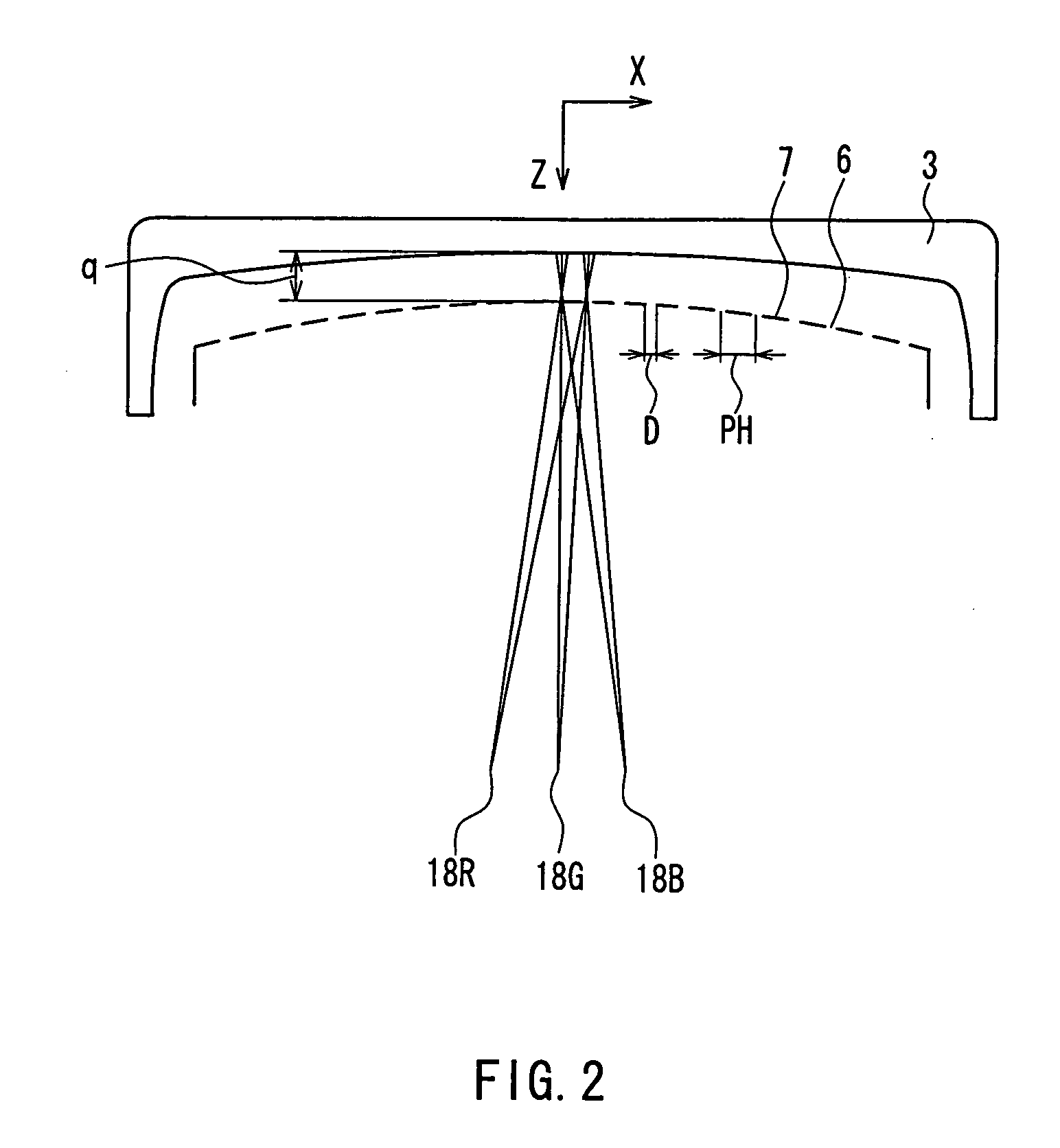
However, in the case where the q value is not set correctly, an appropriate relationship between the interval d and the pitch PHp is broken, with the result that the width of black non-light-emitting layers 17 cannot be kept sufficiently as shown in FIGS. 3B and 3C.
In this case, when the irradiation position of an electron beam is shifted during the operation of the color picture tube, the electron beam irradiates a phosphor stripe of a color other than the desired one (this phenomenon is called “striking of another color”), which is likely to degrade a color purity.
Consequently, the amount of a landing positional shift of the electron beams increases, and the color purity is degraded greatly.
Such an alloy entails high cost, while having a coefficient of thermal expansion of 1 to 2×10⁻⁶ at 0° C. to 100° C., and being effective for suppressing doming.
Furthermore, the iron-nickel alloy has large elasticity after annealing, so that it is difficult to form a curved surface from such an alloy by press forming and to obtain a desired curved surface.
Particularly, in a color picture tube with a flat panel outer surface, the radius of curvature of the shadow mask 7 generally is large, so that press forming is further difficult.
In the case where press forming is insufficient, and undesired stress remains in the shadow mask 7 after press forming, the residual stress changes the shape of the shadow mask 7 in the course of production of the color picture tube, which leads to the landing positional shift of the electron beams, resulting in the significant degradation in color purity.
, which is disadvantageous for doming. P
articularly, in the case of applying the aluminum killed steel to a color picture tube in which the outer surface of the useful portion 1 of the panel 3 is substantially flat, there arises a serious problem such as the significant degradation in color purity.
However, in this color picture tube, a sufficient effect of suppressing doming cannot be obtained.
Furthermore, the effect of suppressing the degradation in color purity during the occurrence of doming is not sufficient, either.
When an attempt is made to obtain a sufficient effect of suppressing doming, the weight of a panel increases, compared with the case of using an expensive Invar material.
Furthermore, the thickness difference between the center and the periphery of the panel increases, so that a panel cracks frequently in a heating process in the course of production.
As a result, even if the doming amount can be suppressed to be small, the distance (margin) between the electron beam whose landing position is shifted due to doming and the phosphor of the second color becomes small, and striking of another color occurs even with a slight doming amount; thus, the color purity is likely to be degraded.
On the other hand, when an iron material that is inexpensive and has satisfactory formability is used, the landing positional shift of the electron beams occurs due to the local doming of the shadow mask during the operation of the color picture tube, and finally, an electron beam overpasses the black non-light-emitting layer to illuminate a phosphor different from the desired one, with the result that the color purity of the color picture tube is degraded.

Method used


Image

  • Color picture tube
  • Color picture tube
  • Color picture tube

Examples


Embodiment Construction

[0044] According to the present invention, a color picture tube can be provided, which has satisfactory visibility, has less degradation in color purity due to doming while having a shadow mask made of an inexpensive material with satisfactory formability, and is excellent in uniformity of brightness.

[0045] Hereinafter, the present invention will be described in detail with reference to the drawings.

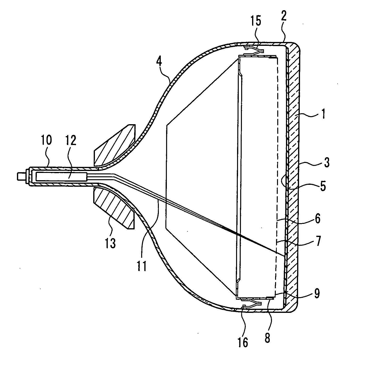
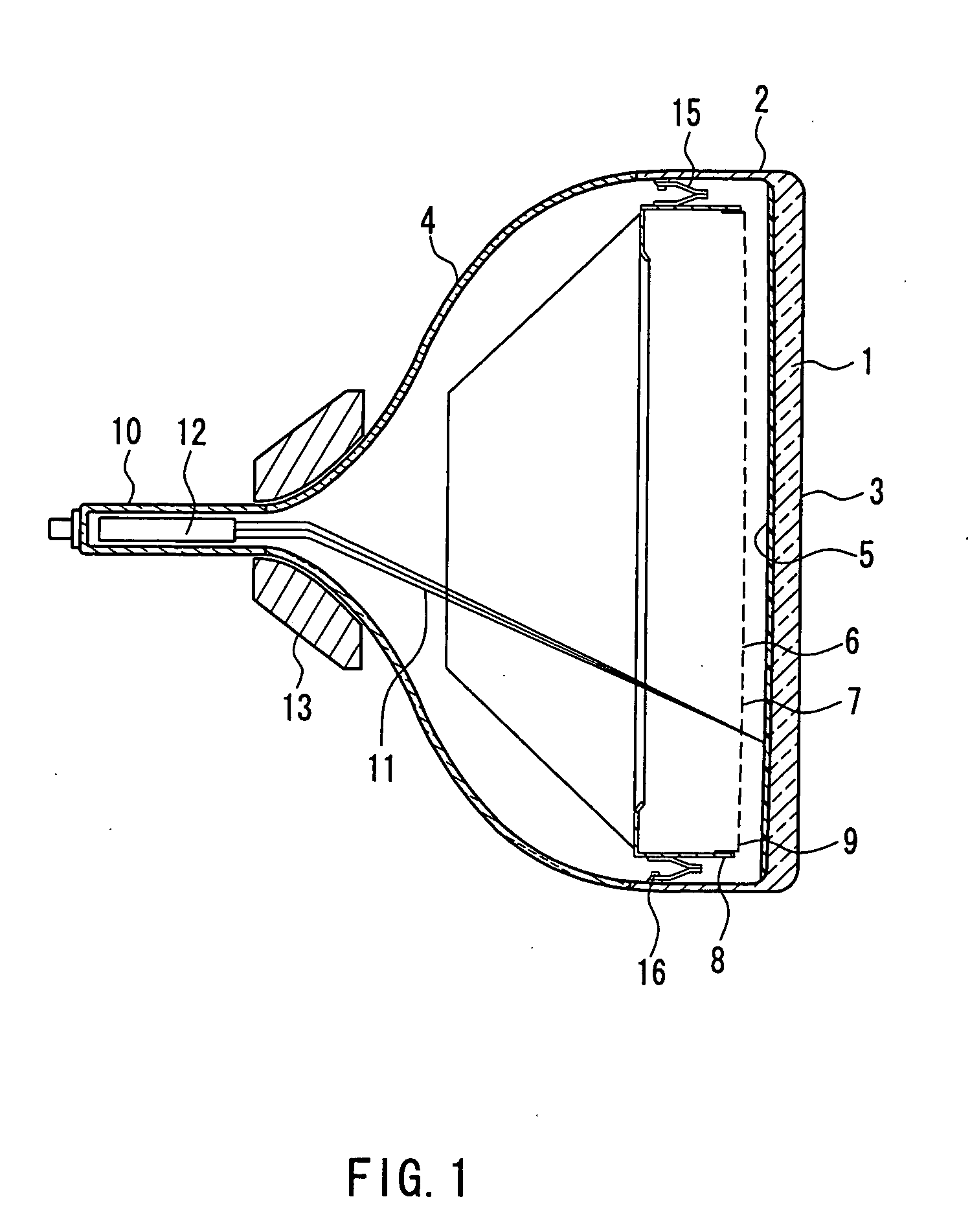
[0046]FIG. 1 is a cross-sectional view of a color picture tube according to one embodiment of the present invention. The color picture tube includes an envelope composed of a panel 3 with a skirt portion 2 provided on the periphery of a substantially rectangular useful portion 1 on which an image is displayed, and a funnel 4 in a funnel shape connected to the skirt portion 2. On an inner surface of the useful portion 1 of the panel 3, a phosphor screen 5 composed of three-color phosphor layers respectively emitting blue, green, and red light is formed. A shadow mask 7 having a substant...


PUM


Abstract

The radius of curvature of an outer surface of a useful portion of a panel is 10,000 mm or more, and a shadow mask is made of a material containing 95% or more of iron. Assuming that a distance (unit: mm) along an X-axis between a center of the panel and a peripheral edge of the useful portion is LH, and a total number of rows of apertures composed of electron beam passage apertures arranged on a straight line substantially parallel to a Y-axis is N, 0.9≦LH / N≦1.0 is satisfied. Furthermore, assuming that a pitch of adjacent rows of apertures is PHC at a center of a perforated region of the shadow mask, PHH at a major axis end of the perforated region, and PHM at a point away from the center of the perforated region by 2 / 3 of a distance MH between the center of the perforated region and the major axis end along the X-axis, PHM / PHC≦1.2 and PHH / PHC≦1.4 are satisfied. Because of this, a color picture tube can be provided, which has satisfactory visibility, has less degradation in color purity due to doming while having a shadow mask made of an inexpensive material with satisfactory formability, and is excellent in uniformity of brightness.

Description

BACKGROUND OF THE INVENTION [0001] 1. Field of the Invention [0002] The present invention relates to a color picture tube having a shadow mask made of a material containing 95% or more of iron, in which a radius of curvature of a panel outer surface is 10,000 mm or more. [0003] 2. Description of Related Art [0004] In general, as shown in FIG. 1, a color picture tube includes an envelope composed of a panel 3 in which a skirt portion 2 is provided on the periphery of a substantially rectangular useful portion 1, and a funnel 4 in a funnel shape connected to the skirt portion 2. A shadow mask 7 having a substantially rectangular perforated region, in which a number of electron beam passage apertures 6 are arranged in vertical and horizontal directions, is placed so as to be opposed to the phosphor screen 5 composed of three-color phosphor layers formed on an inner surface of the useful portion 1 of the panel 3. The shadow mask 7 is held by a mask frame 8 having a substantially rectang...

Claims


Application Information

Patent Timeline
Patent Type & Authority Applications(United States)
IPC IPC(8): H01J29/86H01J29/92
CPCH01J29/07
Inventor SHIMIZU, NORIONIHEI, FUMIAKIMURAI, TAKASHI
Owner MATSUSHITA TOSHIBA PICTURE DISPLAY CO LTD
Learn More