Arithmetic unit

Inactive Publication Date: 2006-03-30
RENESAS TECH CORP
View PDF2 Cites 3 Cited by
  • Summary
  • Abstract
  • Description
  • Claims
  • Application Information

AI Technical Summary

Benefits of technology

[0011] The present invention aims to provide an arithmetic unit performing a saturation process that reduces a delay time relating to an arithmetic process and saturation process, thereby being capable of increasing a processing speed.
[0013] The arithmetic unit of the present invention is configured such that the saturation anticipating section is operated in parallel with respect to the arithmetic processing section, thereby providing an effect of reducing the processing delay at the saturation anticipating section and increasing a processing speed of the arithmetic unit.
[0015] The arithmetic unit according to another aspect of the present invention is configured such that the hit determining section is processed in parallel with the address calculating section, thereby providing an effect of being capable of outputting the Hit signal with high speed.

Problems solved by technology

However, an effect by this pipeline processing is difficult to be shown in an adder, so that the adder may frequently decide a clock cycle of an arithmetic unit.
Further, as explained in the background art, there arises a problem of further delaying the clock cycle by the saturation process if the saturation process is performed by connecting the adding process in serial.
It is considered that the saturation process itself is subject to the pipeline processing, but this has a problem of causing a data hazard or the like, thereby entailing a problem of deteriorating a system performance even by using the pipeline processing to the saturation process of the arithmetic unit.

Method used


Image

  • Arithmetic unit
  • Arithmetic unit
  • Arithmetic unit

Examples


first embodiment

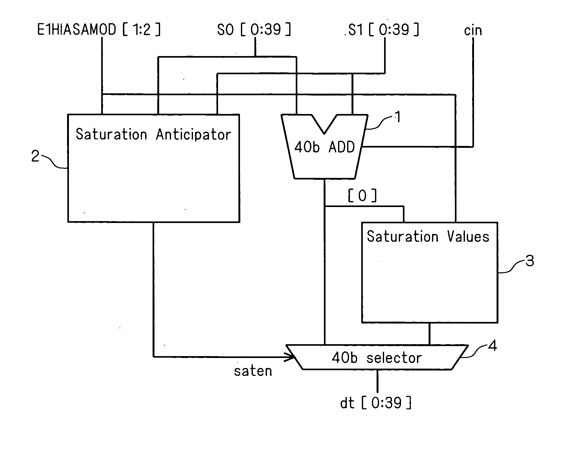
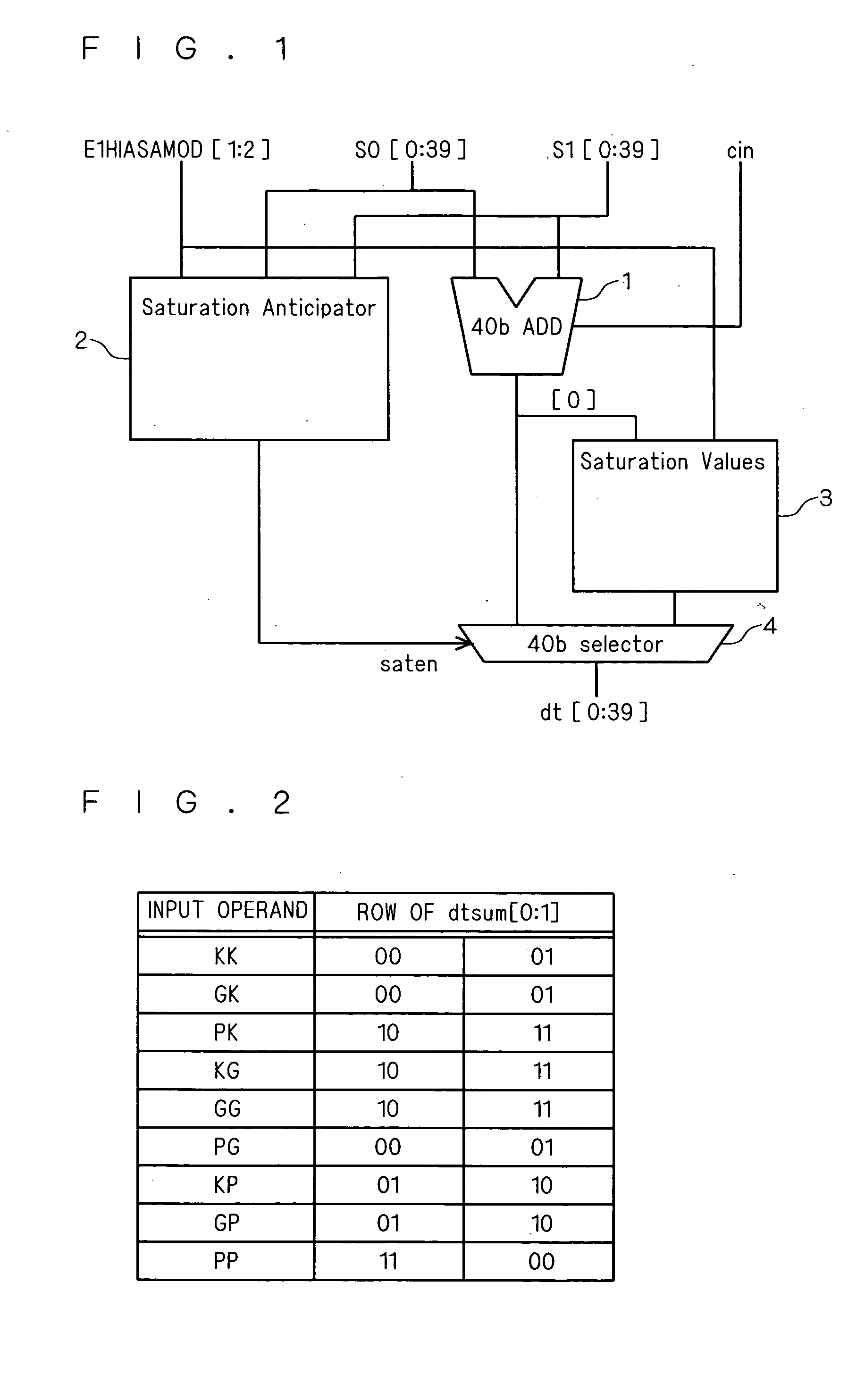
[0035]FIG. 1 is a block diagram showing an arithmetic unit according to this embodiment. The arithmetic unit shown in FIG. 1 has an adder 1, serving as an arithmetic processing section, that performs an add operation of input operands S0[0:39] and S1[0:39] and outputs the arithmetic result dtsum[0:39] and a saturation anticipator 2 that anticipates whether the arithmetic result of the adder 1 is within the representation range of a predetermined bit length (e.g., 16 bit length) or not from the input operands S0[0:39], S1[0:39] and E1HIASAMOD [1:2] and outputs a saturation anticipating signal (saten), wherein the adder 1 serving as an arithmetic processing section and the saturation anticipator 2 are configured to operate in parallel. It should be noted that E1HIASAMOD [1:2] is a signal for setting whether the saturation process including the saturation anticipator 2 is enabled or disabled.

[0036] Further, the arithmetic unit shown in FIG. 1 is provided with a saturation values gener...

second embodiment

[0066] As explained in the first embodiment, the saturation anticipator 2 shown in FIG. 5 utilizes the dtsum[8] and dtsum[32] that are the outputs from the adder 1. However, if the saturation anticipator 2 has to perform plural processes after obtaining the arithmetic result of the dtsum[8] and dtsum[32] from the adder 1, the process at the saturation anticipator 2 does not complete even after the operation at the adder 1 is completed, even if the adder 1 and the saturation anticipator 2 are driven in parallel. Accordingly, it is considered that the process may be delayed in view of the whole arithmetic unit. Therefore, in this embodiment, the arithmetic result from the adder 1 can be utilized at the later process at the saturation anticipator 2, thereby reducing the process after the arithmetic result is obtained. Consequently, the process speed in view of the whole arithmetic unit can be increased.

[0067] Specifically, FIG. 6 shows a view of the configuration of the saturation ant...

third embodiment

[0073] The saturation anticipator 2 according to this embodiment uses a multiplexer, with respect to the saturation anticipator 2 explained in the second embodiment. FIG. 7 shows a view of a specific configuration of the saturation anticipator 2 according to this embodiment. The components in FIG. 7 same as those in FIG. 6 are given same numerals.

[0074] Firstly, 24 E0gen[i] are arranged, and 24 E1gen[i] are also arranged in FIG. 7. The output from E0gen[i] is inputted to the AND circuit 51 every four bit, the outputs from the AND circuit 51 corresponding to E0gen[0] to E0gen[7] are inputted to the AND circuit 52, and the outputs from the AND circuit 51 corresponding to E0gen[8] to E0gen[23] are inputted to the AND circuit 53.

[0075] Similarly, the output from E1gen[i] is inputted to the AND circuit 54 every four bit, the outputs from the AND circuit 54 corresponding to E1gen[0] to E1gen[7] are inputted to the AND circuit 55, and the outputs from the AND circuit 54 corresponding to ...


PUM


Abstract

The present invention provides an arithmetic unit performing a saturation process that can reduce a delay time relating to an arithmetic process and a saturation process, thereby being capable of increasing a processing speed. An arithmetic unit according to the present invention includes an arithmetic processing section that performs an adding or subtracting operation of a first input operand and a second input operand and outputs the arithmetic result, a saturation anticipating section that anticipates whether the arithmetic result is within a representation range of a predetermined bit length based upon the first input operand and the second input operand, and outputs a saturation anticipating signal, and a selecting section selecting that the maximum value or minimum value within the representation range of the predetermined bit length is made to be the output result in case where the arithmetic result is anticipated not to be within the representation range of the predetermined bit length in the saturation anticipating signal from the saturation anticipating section, while selecting that the arithmetic result is made to be the output result in case where the arithmetic result is anticipated to be within the representation range of the predetermined bit length in the saturation anticipating signal. Herein, the saturation anticipating section is operated in parallel with respect to the arithmetic processing section.

Description

BACKGROUND OF THE INVENTION [0001] 1. Field of the Invention [0002] The present invention relates to an arithmetic unit, and more particularly to an arithmetic unit performing a saturation process. [0003] 2. Description of the Background Art [0004] There may be the case in DSP (Digital Signal Processor) that an output is made with a representation range of a bit length different from a representation range of an inputted bit length depending upon a device to be outputted or data type. For example, inputted data within the representation range of 40-bit length may be subject to add-subtract process to be outputted as data within the representation range of 16-bit length in the DSP. In case where the data within the representation range of 40-bit length is outputted as data within the representation range of 16-bit length, it is considered that the output data may cause overflow depending upon the inputted data. As a countermeasure for this overflow, a saturation process is generally ...

Claims


Application Information

Patent Timeline
IPC IPC(8): H03M7/00
CPCG06F7/02G06F7/49921G06F9/342G06F9/3001G06F7/507
Inventor SUZUKI, HIROAKI
Owner RENESAS TECH CORP
Why Eureka
Try Eureka