[0015] The present invention is for methods that can be implemented with
digital circuitry to process the digitized samples of an analog video input so as to accurately and consistently render the individual luminance values for the pixels of a high-resolution image. The invention comprises two fundamental methods for rendering each pixel of the video input (or each color component of each pixel) with, generally, a single digitized sample of the analog input. These methods are designated herein as a “global
phase adjustment algorithm” and a “local phase adjustment
algorithm.” They can eliminate, or reduce the probability of,
dynamic display anomalies by avoiding the use of samples that occur during the transition times between the input pixels. Although a given design could employ either one of these algorithms by itself, the algorithms are complementary and were developed to work in concert.
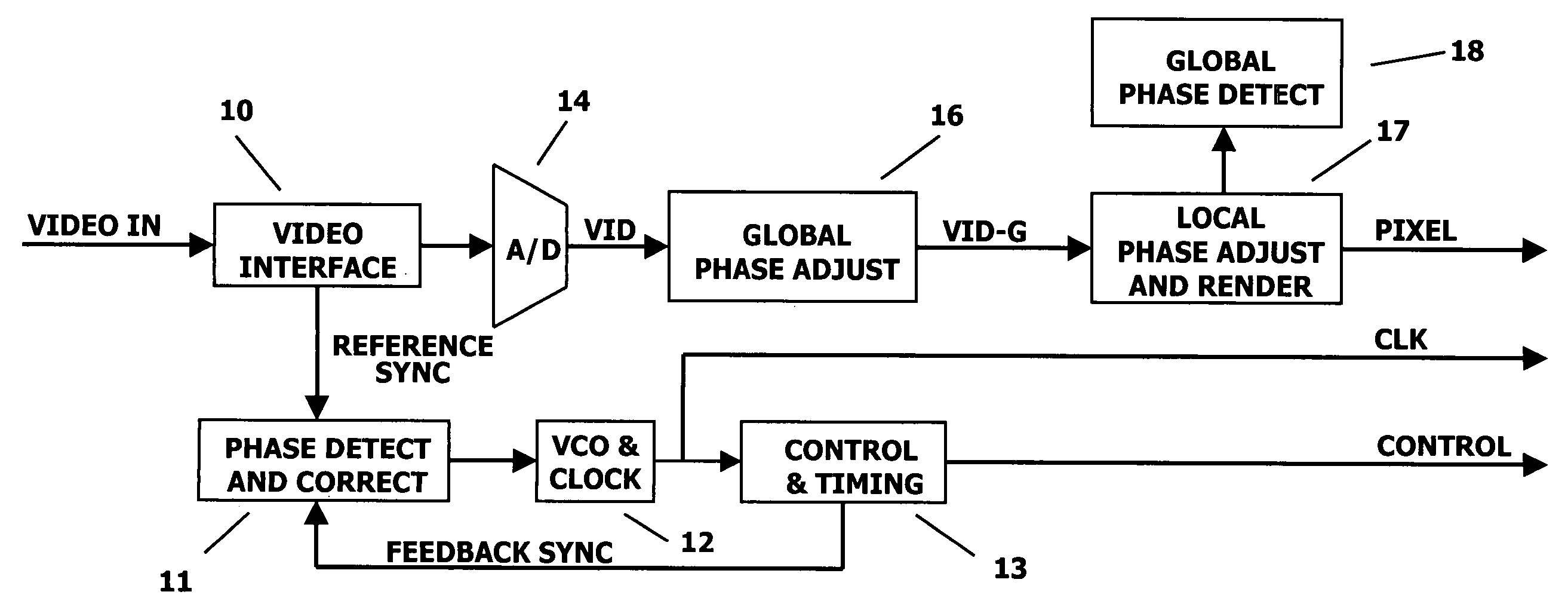
[0017] The invention employs an A-to-D sampling clock that is used to process analog video and that is generated by a PLL circuit that locks the phase of this clock to the horizontal
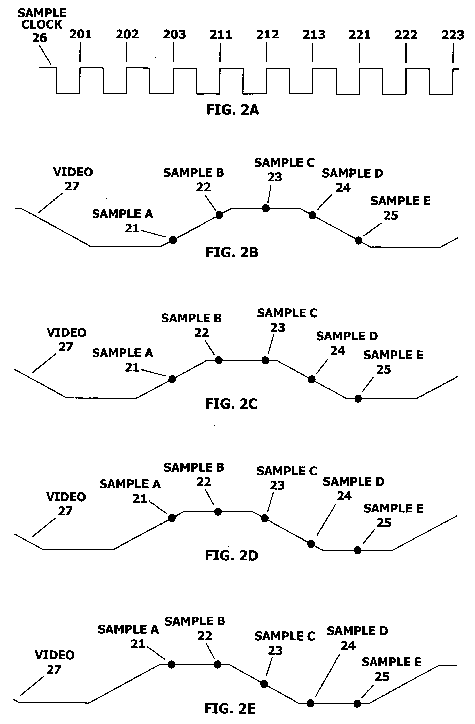
sync of the video input. The invention employs over-sampling, whereby the frequency of the sampling clock is an integer multiple of the rate of the input pixels in the analog video signal. An integer number of digitized video samples are then generated from a sampling A-to-D converter for each of the input pixels (i.e., one sample for each of the multiple phases of the sampling clock that occur during each pixel time-period). The PLL circuit is designed so that, at nominal timing, a specific
clock phase occurs near the center of the stable time-period for each of the input pixels. The
video image can be captured by selecting this specific
clock phase to render each of the input pixels with the sampled output from the A-to-D converter that occurs on this clock phase. With a sufficiently stable sampling clock, this will result in an accurate and high-quality rendering of the image. But if the relative timing between the input video and the sampling clock becomes misaligned so that the selected clock phase occurs within the transition regions between the pixels, dynamic display anomalies will result.
[0020] The local phase adjustment algorithm renders each display pixel by selecting, generally, a
single sample from the A-to-D converter from a group of available samples that occur over a relatively small time window that brackets a “nominally correct time” for sampling the pixel. A preferred embodiment of this algorithm determines the differences in the sampled values between every pair of contiguous samples from the A-to-D converter. The relative magnitudes between all of the contiguous difference values are then compared in order to determine locations within the digitized video sample
stream that may be close to a video transition region between two adjacent input pixels. When the result of these magnitude comparisons indicates that the nominally correct sample time for an input pixel may be close to, or within, a video transition region, the pixel is rendered with an alternate nearby sample that is less likely to be located within a video transition region. By avoiding the use of samples that occur during video transition regions, the local phase adjustment algorithm increases the tolerance of the rendering circuit to video timing errors that can generate dynamic anomalies in the rendered display image.
[0021] If the local phase adjustment algorithm were used by itself, without the global phase adjustment algorithm, then the nominally correct sample for each pixel would always occur at the same fixed clock phase (i.e., the same fixed clock phase for every video
refresh cycle, as well as for all the-pixels within a given
refresh cycle). When the local phase adjustment algorithm detects that the nominally correct sample for a given pixel might be within a video transition region, it renders the pixel with an alternate sample that is located a slight distance in phase from the nominal sample. In this way, the local phase adjustment algorithm can compensate for relatively small errors in the
phase alignment of the video input that can occur over relatively short time durations. For example, it can adjust for
jitter in the sample clock and it can adjust for a
phase drift in the sample clock that occurs over the horizontal cycle of the video input. Because these types of phase errors occur over a relatively short time-period, they cannot be corrected by the global phase adjustment algorithm. However, the local phase adjustment algorithm can only adjust for phase errors of relatively small magnitudes, whereas the global phase adjustment algorithm can adjust for large phase errors, provided that these
phase offset errors are either constant or change only slowly over time. Therefore, the two algorithms of this invention are complementary, and they can be used together to completely eliminate dynamic artifacts in the rendering of a high-resolution image from an analog video input.

