
Semiconductor substrate thinning method for manufacturing thinned die

a technology of semiconductors and substrates, applied in semiconductor devices, semiconductor/solid-state device details, electrical devices, etc., can solve the problems of severe crystal damage, insufficient heat removal of stacked die packages, and bumps disposed on the front side being subject to mechanical loads, so as to reduce the thickness of the bumped substra

Active Publication Date: 2006-03-30
ADVANCED MICRO DEVICES INC
View PDF48 Cites 48 Cited by
  • Summary
  • Abstract
  • Description
  • Claims
  • Application Information

AI Technical Summary

Benefits of technology

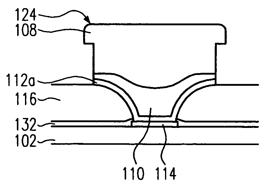
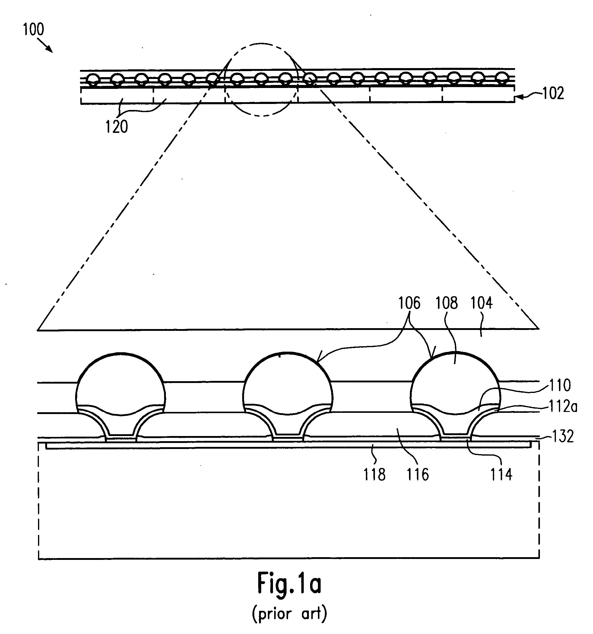
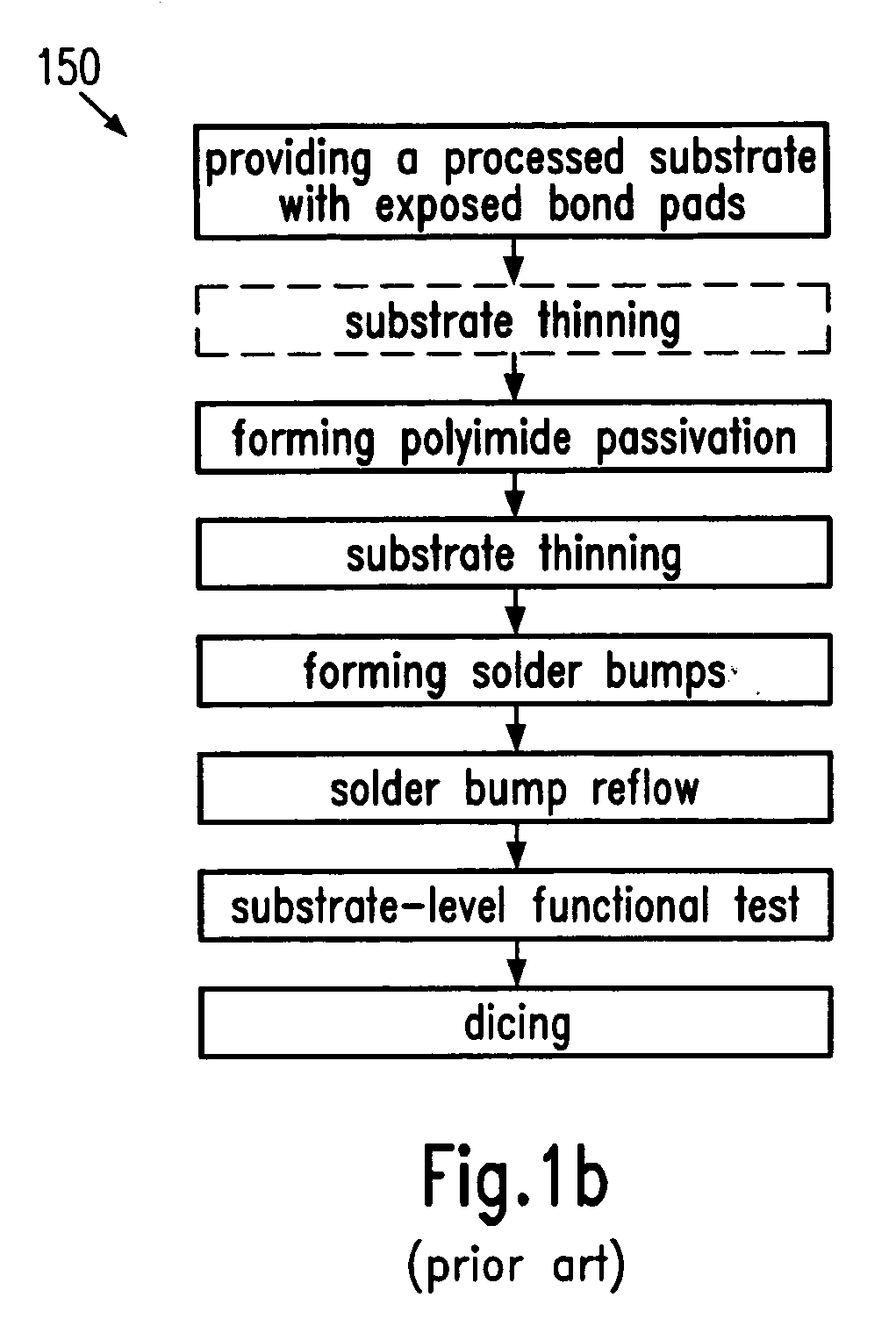
[0029] According to one illustrative embodiment of the present invention, a method of thinning of a processed semiconductor substrate is provided. The method comprises providing a semiconductor substrate having formed thereon a plurality of exposed contact pads and forming solder bumps over the plurality of contact pads. The method further comprises reducing the thickness of the bumped substrate and performing a solder reflow process after thinning of the substrate.

Problems solved by technology

For high power applications, heat removal in stacked die packages is not sufficient.
In particular, grinding of substrates provided with solder bumps is a major concern in manufacturing thin die for flip-chip bond applications since, during backside grinding, the bumps disposed on the front side are also subjected to mechanical load and consequently may be damaged.
This process, however, leaves a rather rough backside surface and causes severe crystal damage in a region close to the ground backside surface(sub-surface) reaching to a depth of approximately 5-30 μm (depending on the characteristic of the grinding tools used).
These tiny cracks, however, introduce stress and dramatically reduce the stability of the substrate 102 and heighten the bowing of the substrate 102.
Thus, any severe substrate damage, e.g., breakage of the substrate 102, involves substantial costs.
Handling / transferring of thinned substrates 102, however, even with adapted equipment, increases the risk of breakage of the substrate 102.
Additionally, the adaptation of the equipment increases the manufacturing costs.
Thinning of individual die, however, is a cost- and time-consuming operation that does, in addition, not meet the desired thickness uniformity requirements.
Furthermore, the substrate thinning process impairs the solder bumps 106, in particular when a grinding method is employed, even when the bumped side is laminated by a conventional bump protection tape 104.
For some applications, depending on the employed solder bump material, for example, for microprocessor applications comprising typically solder bump materials with high lead content (greater than 90%), the damage is, in general, unacceptably high and leads to high yield loss.
Deposition of an additional protection layer to entirely embed the formed solder bumps 106, for example, by means of spin-coat deposition, is time- and cost-consuming and bears the risk of adversely affecting the bumped substrate 102, for example, by inducing thermal stress or by contamination.
Consequently, backside grinding is performed before or after the polyimide application, although the high risk of breakage of the thinned substrates 102 during the huge number of processing and handling steps, and the demand for special handling / transferring equipment for thinned substrates 102 in the bumping, reflowing, testing and dicing processes, reduces the cost-effectiveness of the process.

Method used


Image

  • Semiconductor substrate thinning method for manufacturing thinned die
  • Semiconductor substrate thinning method for manufacturing thinned die
  • Semiconductor substrate thinning method for manufacturing thinned die

Examples


Embodiment Construction

[0036] Illustrative embodiments of the invention are described below. In the interest of clarity, not all features of an actual implementation are described in this specification. It will of course be appreciated that in the development of any such actual embodiment, numerous implementation-specific decisions must be made to achieve the developers' specific goals, such as compliance with system-related and business-related constraints, which will vary from one implementation to another. Moreover, it will be appreciated that such a development effort might be complex and time-consuming, but would nevertheless be a routine undertaking for those of ordinary skill in the art having the benefit of this disclosure.

[0037] The present invention will now be described with reference to the attached figures. Various structures, systems and devices are schematically depicted in the drawings for purposes of explanation only and so as to not obscure the present invention with details that are we...


PUM


Abstract

In a method according to the present invention, a substrate thinning process is performed on a bumped substrate prior to the ultimate solder reflow process to heal bump defects caused by the substrate thinning process. Concurrently, the risk of substrate breakage is reduced compared to the prior art process since the number of process steps, requiring handling of thinned substrates, is reduced.

Description

BACKGROUND OF THE INVENTION [0001] 1. Field of the Invention [0002] The present invention relates to the field of the fabrication of semiconductor devices, and, more particularly, to a method of manufacturing thinned die for flip-chip applications by employing a substrate thinning process to reduce the thickness of substrates bearing, for instance, a plurality of die for forming integrated circuits. [0003] 2. Description of the Related Art [0004] There is an ongoing trend in the semiconductor industry to increase the size of substrates employed in the manufacturing process. Currently, 400 mm substrates are intended for industrial application for large scale production technologies, for example, for memory or microprocessor devices. To ensure safe and readily practicable substrate handling during the entire manufacturing process, the thickness of the larger substrates is also increased. Thus, 400 mm substrates typically have a thickness of approximately 800 μm, whereas, for example, ...

Claims


Application Information

Patent Timeline
IPC IPC(8): H01L21/302H01L21/461
CPCH01L21/304H01L24/02H01L2924/0002H01L2224/05572H01L2924/01072H01L2924/01033H01L2924/01024H01L2924/01023H01L2924/01006H01L2224/05559H01L2224/05018H01L2224/05027H01L24/03H01L24/05H01L24/11H01L24/12H01L2224/03912H01L2224/0401H01L2224/05083H01L2224/05624H01L2224/05644H01L2224/05647H01L2224/1147H01L2224/13099H01L2224/131H01L2924/01005H01L2924/01013H01L2924/01014H01L2924/01015H01L2924/01018H01L2924/01022H01L2924/01028H01L2924/01029H01L2924/0103H01L2924/01042H01L2924/01046H01L2924/0105H01L2924/01075H01L2924/01077H01L2924/01078H01L2924/01079H01L2924/01082H01L2924/01327H01L2924/014H01L2924/05042H01L2924/14H01L2924/19043H01L2924/3025H01L2924/00014H01L2224/05552H01L2924/351H01L2224/0392H01L24/13H01L2221/6834H01L2224/11849H01L21/6836H01L2221/68327H01L2224/0347H01L2224/0361H01L2924/00
Inventor SELIGER, FRANKLEHR, MATTHIASWIELAND, MARCELMERGILI, LOTHARKUECHENMEISTER, FRANK
Owner ADVANCED MICRO DEVICES INC
Features
  • Generate Ideas
  • Intellectual Property
  • Life Sciences
  • Materials
  • Tech Scout
  • Unparalleled Data Quality
  • Higher Quality Content
  • 60% Fewer Hallucinations
Learn More