Receiver, receiving method and portable wireless apparatus
a wireless receiver and receiver technology, applied in the direction of pulse technique, amplitude demodulation, line-faulst/interference reduction, etc., can solve the problem of bit errors in demodulated data, and achieve accurate calibration, reduce the time for integration of calculations, and reduce the effect of repeated operation calibration tim
- Summary
- Abstract
- Description
- Claims
- Application Information
AI Technical Summary
Benefits of technology
Problems solved by technology
Method used
Image
Examples
first embodiment
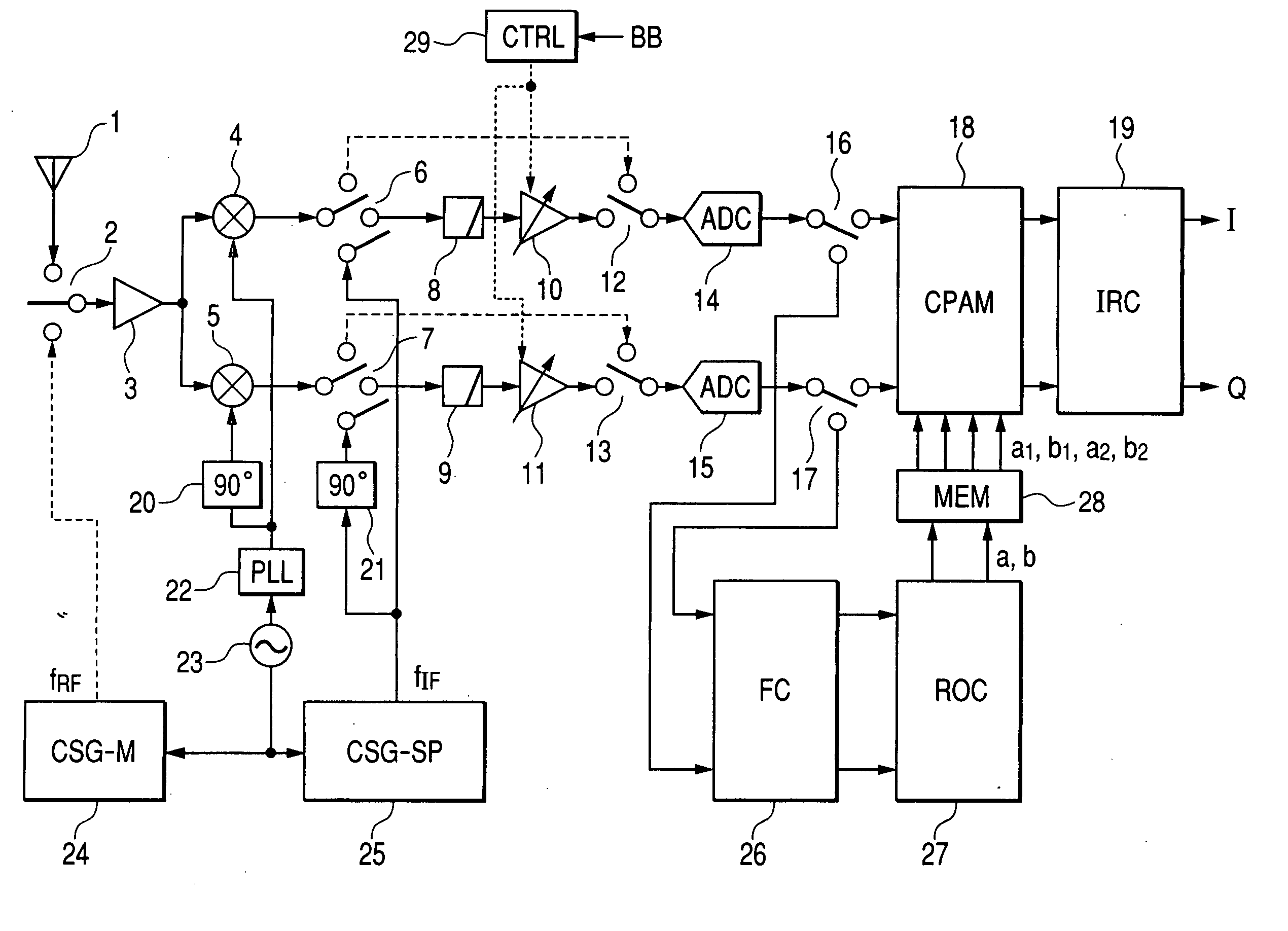
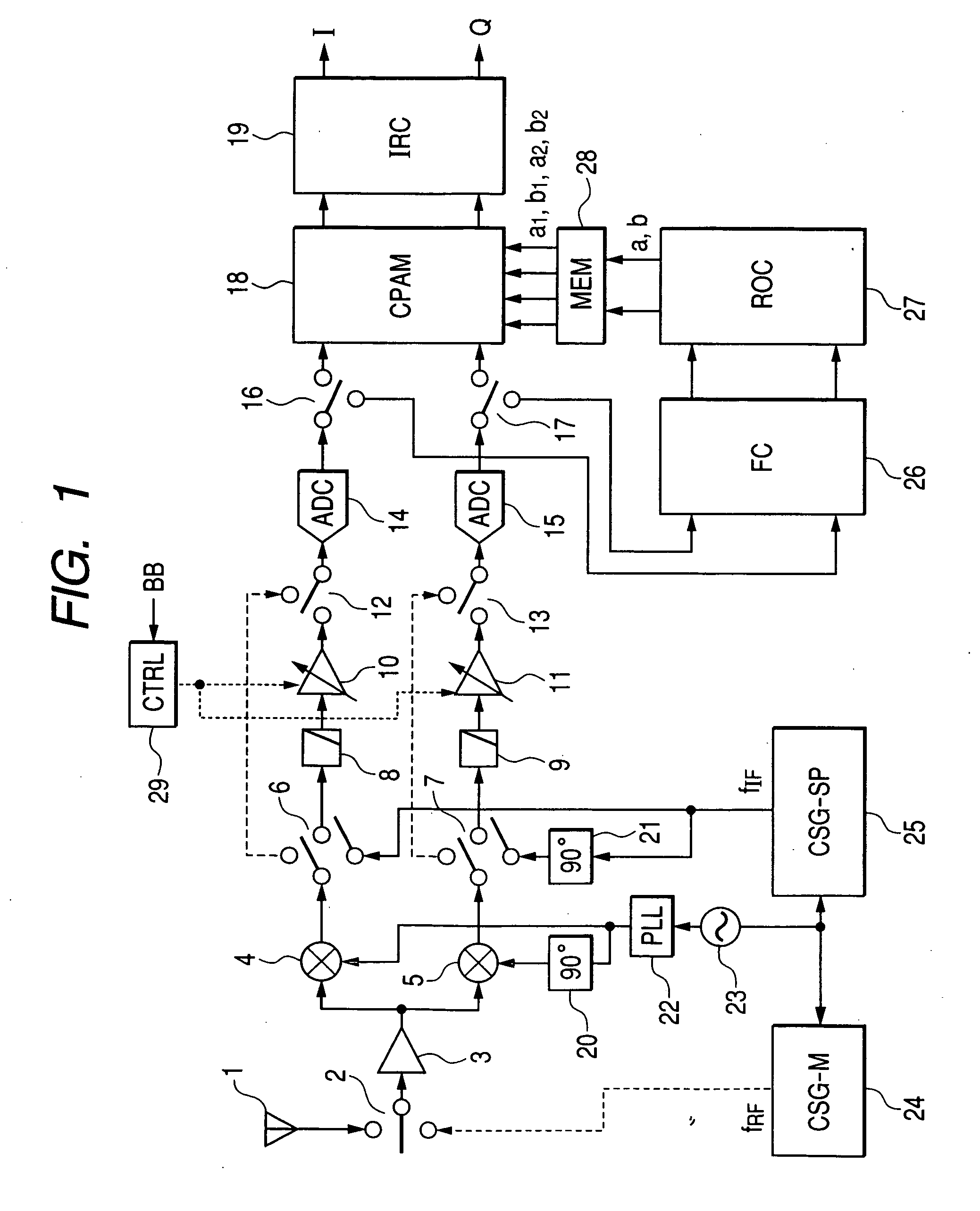
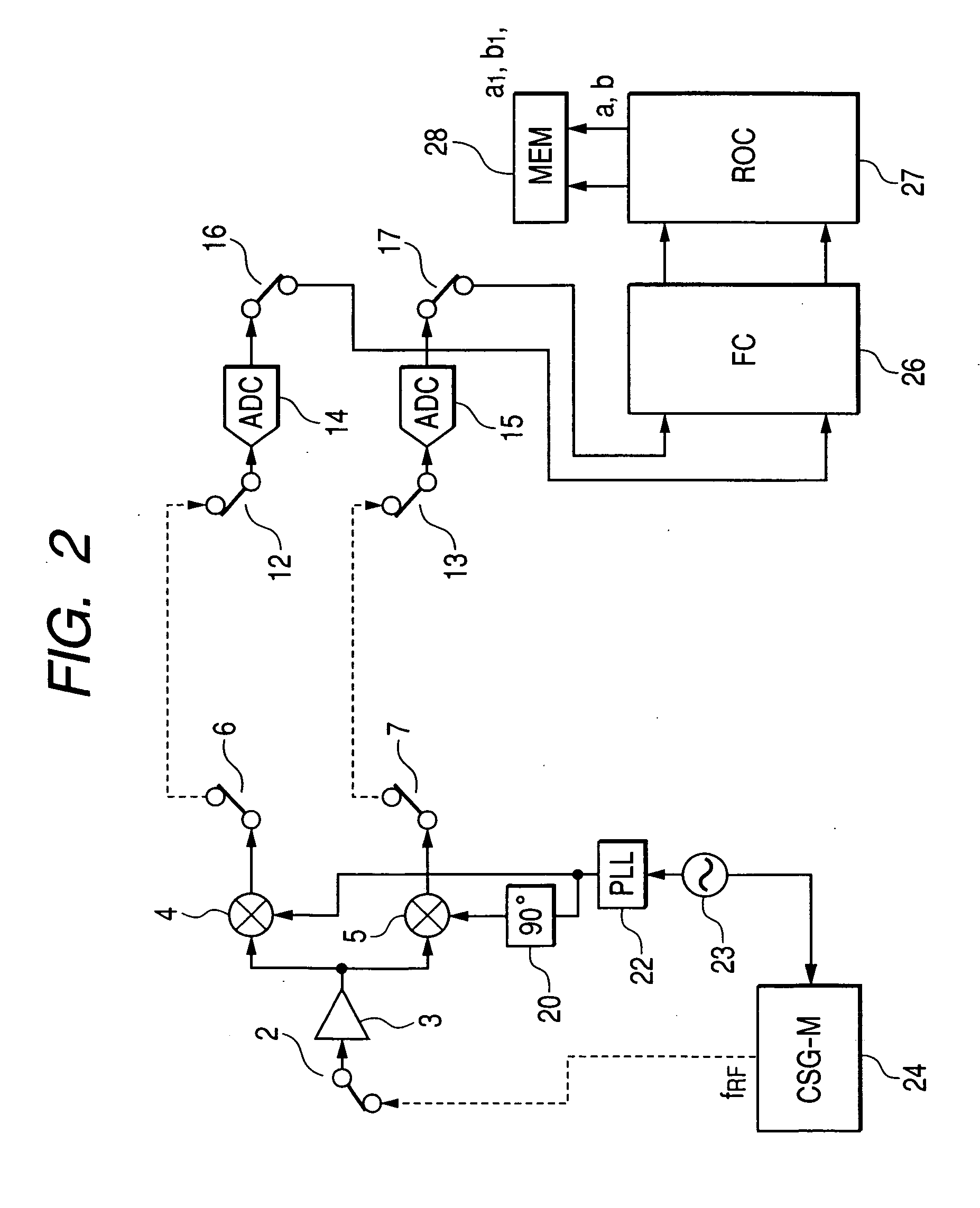
[0042]FIG. 1 shows a first embodiment of the present invention. This embodiment is a receiver using the low-IF system. The low-IF receiver shown in FIG. 1 comprises an antenna 1, switches 2, 6, 7, 12, 13, 16, and 17, an LNA 3, mixers 4 and 5, low-pass filters 8 and 9, automatic gain controlled amplifiers 10 and 11, analog-digital converters 14 and 15, a calibration circuit for phase and amplitude mismatch (CPAM) 18, an image rejection circuit (IRC) 19 which outputs in-phase (I) and quadrature (Q) components of baseband signals, 90-degree phase shifters 20 and 21, a PLL 22, a crystal oscillator 23, a calibration signal generator for mixer (CSG-M) 24 which generates a calibration signal with a radio frequency (first frequency) fRF, a calibration signal generator for signal path (CSG-SP) 25 which generates a calibration signal with an IF frequency (second frequency) fIF, a frequency converter (FC) 26, a memory (MEM) 28, a repeated operation circuit (ROC) 27, and a control circuit 29.
[...
second embodiment
[0084]FIG. 13 shows a second embodiment of the present invention. This embodiment is a receiver using the zero-IF system. The zero-IF receiver shown in FIG. 13 comprises an antenna 110, switches 111, 115, 116, 121, 122, 125, and 126, an LNA 112, mixers 113 and 114, low-pass filters 117 and 118, automatic gain controlled amplifiers 119 and 120, analog-digital converters 123 and 124, a calibration circuit for phase and amplitude mismatch 127, 90-degree phase shifters 128 and 129, a PLL 130, a crystal oscillator 131, a calibration signal generator for mixer 132, a calibration signal generator for signal path 133, a frequency converter 134, a memory 136, and a repeated operation circuit 135.
[0085] In the receiver shown in FIG. 13, the PLL 130 generates carriers in an RF band and received signals are directly frequency converted into baseband signals. In the zero-IF system, because interfering waves (image signals) which are frequency converted are not present in the same frequency band...
third embodiment
[0094]FIG. 19 shows a third embodiment of the present invention. This embodiment is a receiver compatible with GSM / EDGE / W-CDMA standards The receiver compatible with GSM / EDGE / W-CDMA standards shown in FIG. 19 comprises an antenna 301, switches 302, 306, 307, 312, 313, 316, 317, 334, and 335, an LNA 303, mixers 304 and 305, variable low-pass filters 308 and 309, automatic-gain controlled amplifiers 310 and 311, analog-digital converters 314 and 315, a calibration circuit for phase and amplitude mismatch 318, 90-degree phase shifter 320 and 321, a PLL 322, a crystal oscillator 323, a calibration signal generator for mixer 324, a calibration signal generator for signal path 325, a frequency converter 326, a memory 328, a repeated operation circuit 327, high-pass filters 330, 331, 332, and 333, and low-pass filters 336 and 337.
[0095] The receiver configured as above operates in an optimum communication scheme which is selected from among GSM, EDGE and W-CDMA standards by the baseband (...
PUM
 Abstract
Description
Claims
Application Information
 - R&D
- Intellectual Property
- Life Sciences
- Materials
- Tech Scout
- Unparalleled Data Quality
- Higher Quality Content
- 60% Fewer Hallucinations
Browse by: Latest US Patents, China's latest patents, Technical Efficacy Thesaurus, Application Domain, Technology Topic, Popular Technical Reports.
© 2025 PatSnap. All rights reserved.Legal|Privacy policy|Modern Slavery Act Transparency Statement|Sitemap|About US| Contact US: help@patsnap.com


