Lubricating oil supplying system for internal combustion engine

a technology of lubricating oil and internal combustion engine, which is applied in the direction of auxiliaries, machines/engines, functional valve types, etc., can solve the problems of unavoidable rise in production costs, negative pressure between these pumps, and complicated structure of oil pressure passages, etc., and achieve the effect of simplifying the hydraulic circui

Inactive Publication Date: 2006-04-06
HITACHI LTD
View PDF13 Cites 34 Cited by
  • Summary
  • Abstract
  • Description
  • Claims
  • Application Information

AI Technical Summary

Benefits of technology

[0004] In the above conventional lubricating oil supplying system, the above electric pump is disposed at the downstream side of the driven pump and located in series with the driven pump through the above heat accumulative container, so that the lubricating oil sucked in and discharged from the driven pump is directly sent to the electric pump. Consequently, it is not required that each pump separately sucks lubricating oil from the lubricating oil tank. As a result, there is a merit of simplifying a hydraulic circuit. However, if the amount of the lubricating oil discharged from the driven pump exceeds that from the electric pump, a negative pressure is developed between these pumps. In view of this, a check valve is provided to the above heat accumulative container to introduce a low pressure therein, so that the above negative pressure can be prevented from being developed.

Problems solved by technology

However, if the amount of the lubricating oil discharged from the driven pump exceeds that from the electric pump, a negative pressure is developed between these pumps.
This hydraulic passage must be formed relatively long, so that the structure of oil pressure passages is complicated.
As a result, manufacturing or production operation for the lubricating oil supplying system becomes troublesome so that a production cost unavoidably rises.

Method used


Image

  • Lubricating oil supplying system for internal combustion engine
  • Lubricating oil supplying system for internal combustion engine
  • Lubricating oil supplying system for internal combustion engine

Examples


Embodiment Construction

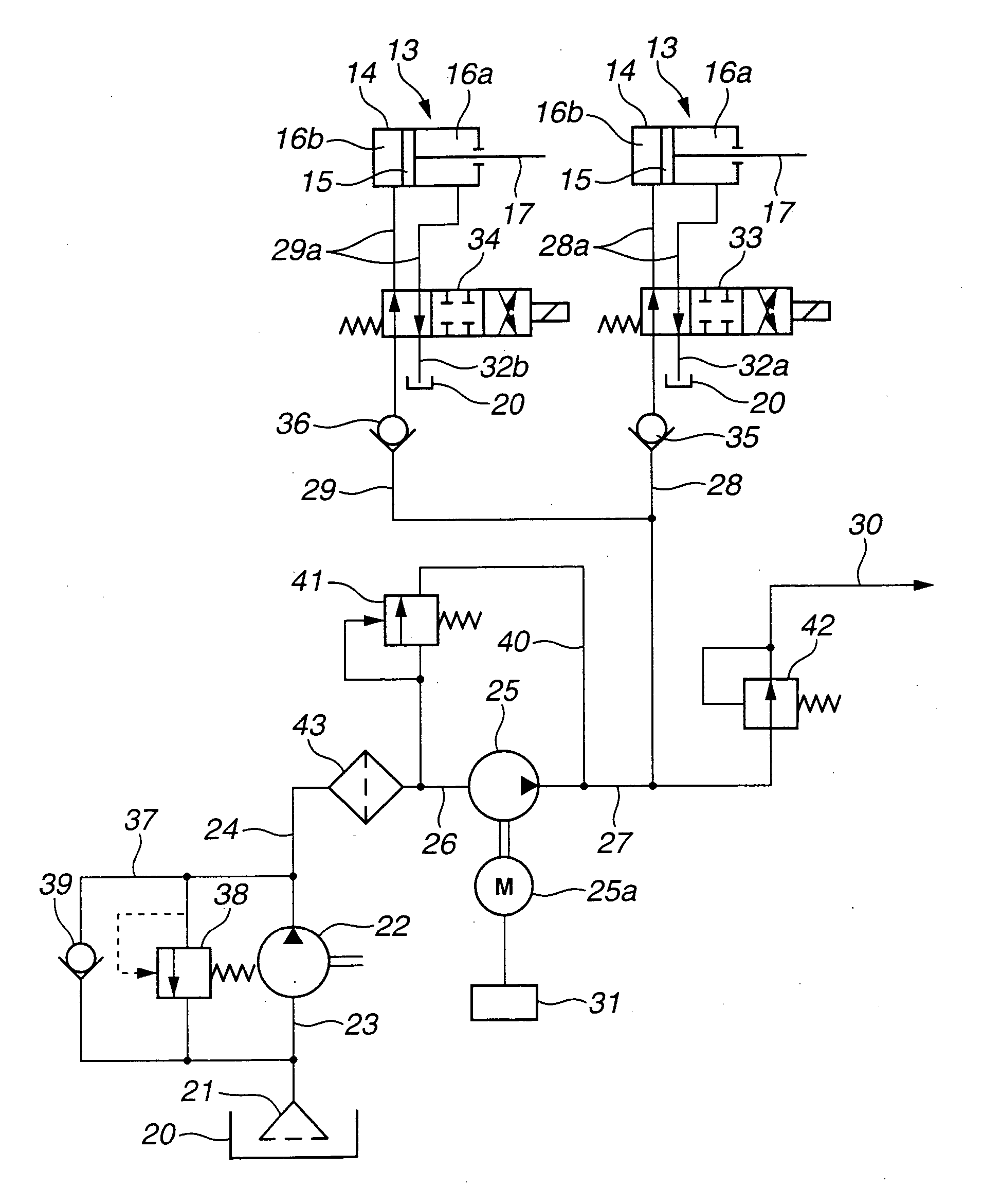
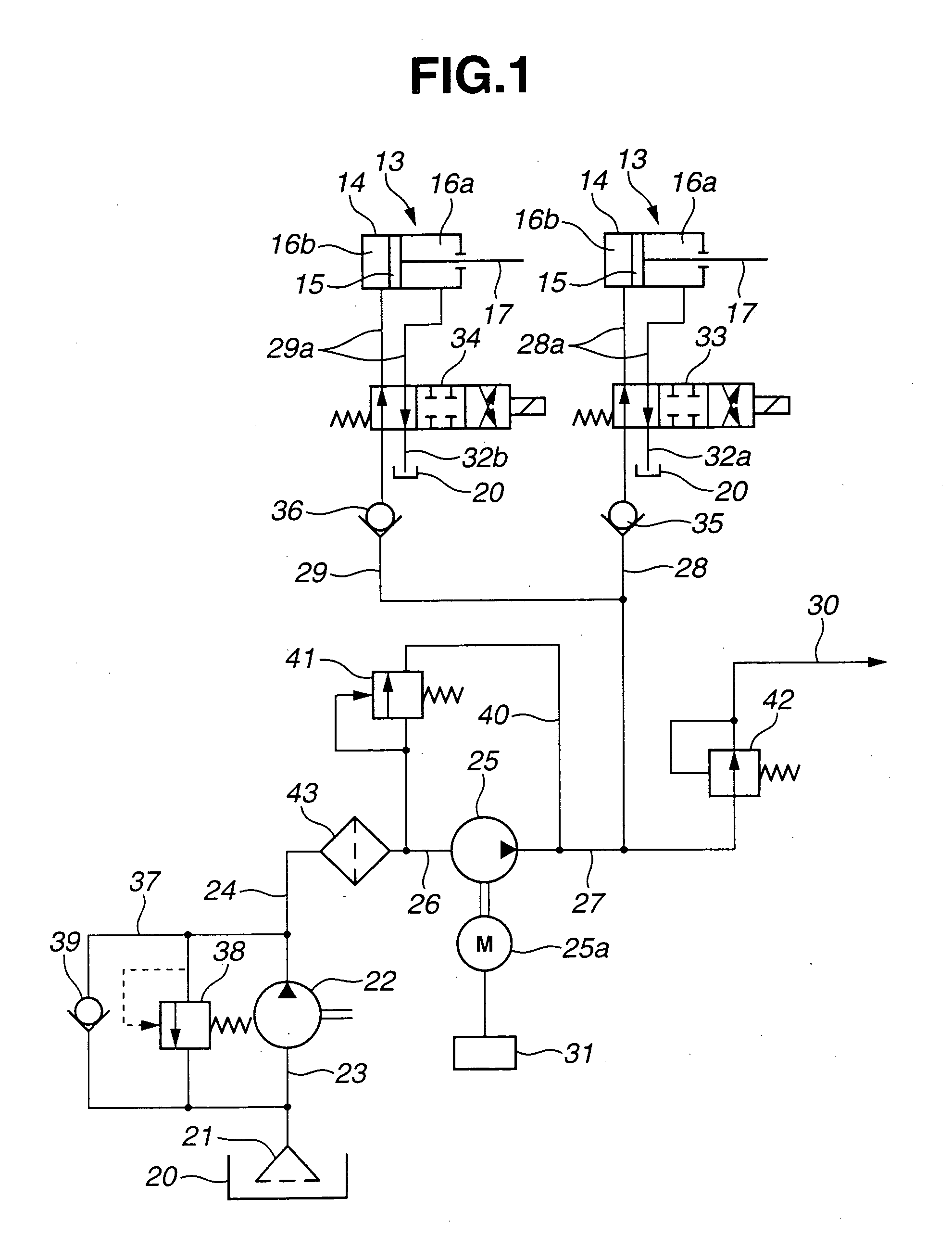
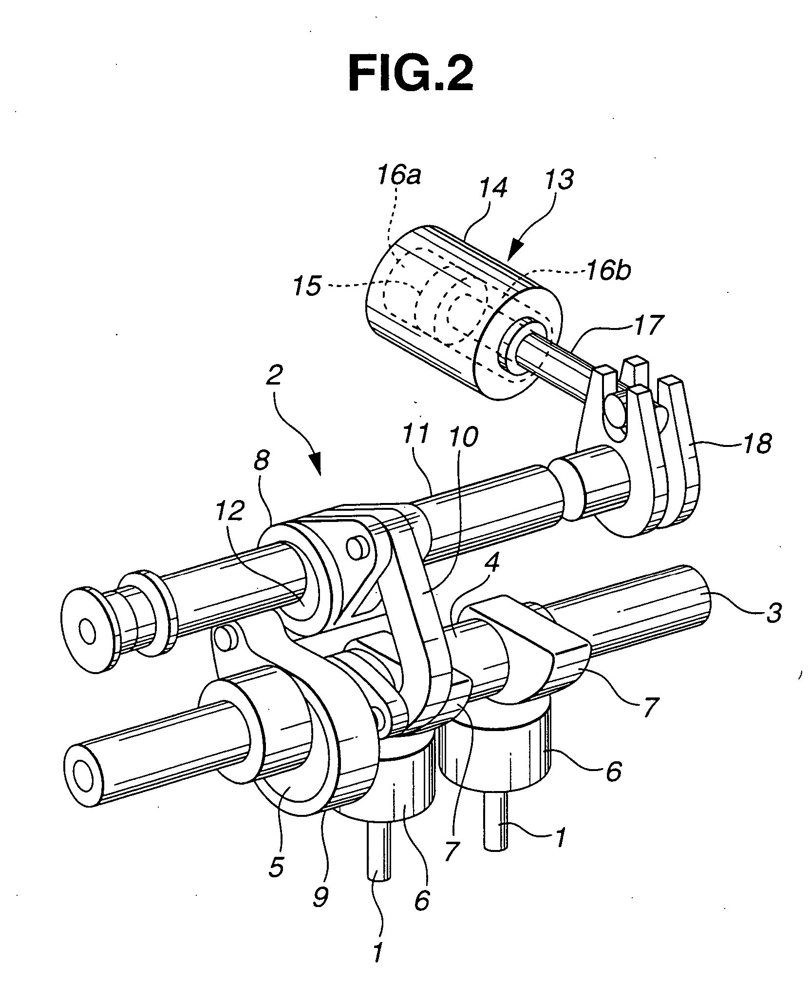
[0019] Referring now to FIGS. 1 to 5, an embodiment of a lubricating oil supplying system for internal combustion engine, according to the present invention is illustrated. Firstly, the internal combustion engine is a multi-cylinder V-type engine, in which two intake valves 1, 1 are provided for each (engine) cylinder so as to be slidably supported by a cylinder head (not shown). The valve lift of each intake valves 1, 1 is variably controlled in accordance with an engine operating condition under the action of a variable valve lift mechanism 2 as shown in FIG. 2.

[0020] This variable valve lift mechanism 2 is the same as that disclosed in Japanese Patent Provisional Publication No. 2001-214765 whose assignee is the same as that in the present application, so that explanation thereof will be briefly made. Japanese Patent Provisional Publication No. 2001-214765 is incorporated herein by reference. In the variable valve lift mechanism 2, driving shaft 3 whose inside is hollow is arran...


PUM


Abstract

A lubricating oil supplying system for an internal combustion engine includes a lubricating oil storage section for storing lubricating oil. A driven pump is driven by the internal combustion engine to suck the lubricating oil from the lubricating oil storage section and discharge the lubricating oil to a discharge passage. An electric pump is provided for sucking the lubricating oil discharged from the driven pump to the discharge passage and discharge the lubricating oil to a lubricating oil requiring section in the internal combustion engine. A controlling mechanism is provided for drivingly controlling the electric pump in accordance with a control signal. A bypass passage is provided for bypassing the driven pump. A check valve is disposed in the bypass passage to allow the lubricating oil in the lubricating oil storage section to flow only through a path bypassing said driven pump and toward side of the discharge passage.

Description

BACKGROUND OF THE INVENTION [0001] This invention relates to improvements in a lubricating oil supplying system for an internal combustion engine, arranged to supply lubricating oil to various sliding sections, a variable valve actuation mechanism or the like in the internal combustion engine under the action of an oil pump driven by the internal combustion engine and an electric pump driven by an electric motor. [0002] Hitherto, various types of the lubricating oil supplying systems are proposed and put into practical use. One of such lubricating oil supplying apparatuses is disclosed in a Japanese Patent Provisional Publication No. 2003-148120. Briefly, this lubricating oil supplying system includes a variable valve actuation mechanism serving as a driving device, disposed to a main body of an internal combustion engine. A variable valve actuation mechanism and various sliding sections are supplied with lubricating oil stored in a lubricating oil tank. The lubricating oil stored w...

Claims


Application Information

Patent Timeline
Patent Type & Authority Applications(United States)
IPC IPC(8): F01M11/02F01M1/04
CPCF01L1/46F01L13/0026F01L2013/0073F01M1/02F01M2001/0215F01M2001/123Y10T137/7777Y10T137/7774
Inventor HARA, SEINOSUKE
Owner HITACHI LTD
Why Eureka
Try Eureka