Internal combustion engine producing low emissions

a combustion engine and low emission technology, applied in the field of improved engines, can solve the problems of engine designers, emissions exceeding the acceptable limit, and another standard being exceeded, and achieve the effect of reducing undesirable engine emissions sufficiently

Inactive Publication Date: 2006-04-06
CUMMINS INC
View PDF41 Cites 66 Cited by
  • Summary
  • Abstract
  • Description
  • Claims
  • Application Information

AI Technical Summary

Benefits of technology

[0013] It is, therefore, one object of the present invention to overcome the deficiencies of the prior art and to provide an internal combustio

Problems solved by technology

Modifications made to meet one standard may lead to increased emissions of a type that cause another standard to be exceeded.
Thus designers are often confronted with not only the challenge of meeting a newly imposed emission standard but to do so in a way that does not cause other emissions standards, previously met or newly imposed, to be exceeded.
An example of the difficulties created for engine designers is that created by a new set of diesel engine emissions standards/limits mandated by the Environmental Protection Agency for application in the U.S. market.
However, such changes can often adversely affect one or more other emissions possibly causing the emissions to exceed the acceptable limit.
This problem is accentuated by the need to achieve other critical engine operating characteristics such as fuel economy, high torque output, low operating costs and/or reduced maintenance.
As one example, the amount of soot that is entrained in the engine's lubrication oil can have a profound effect on the cost of operation and the length of service before a major overhaul is required.
Soot is very abrasive and can cause high wear if allowed to become entrained in the engine's lubrication oil to any substantial degree.
The amount of soot entrained in the engine's lubrication oil can be affected by a number of factors such as combustion chamber shape and fuel injection spray angle but changes in these variables can have the undesired effect of actually increasing emissions entrained in the engine's lubrication oil.
However, none of t

Method used


Image

  • Internal combustion engine producing low emissions
  • Internal combustion engine producing low emissions
  • Internal combustion engine producing low emissions

Examples


Embodiment Construction

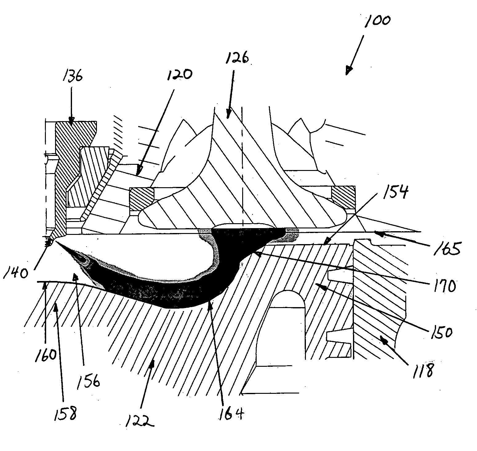
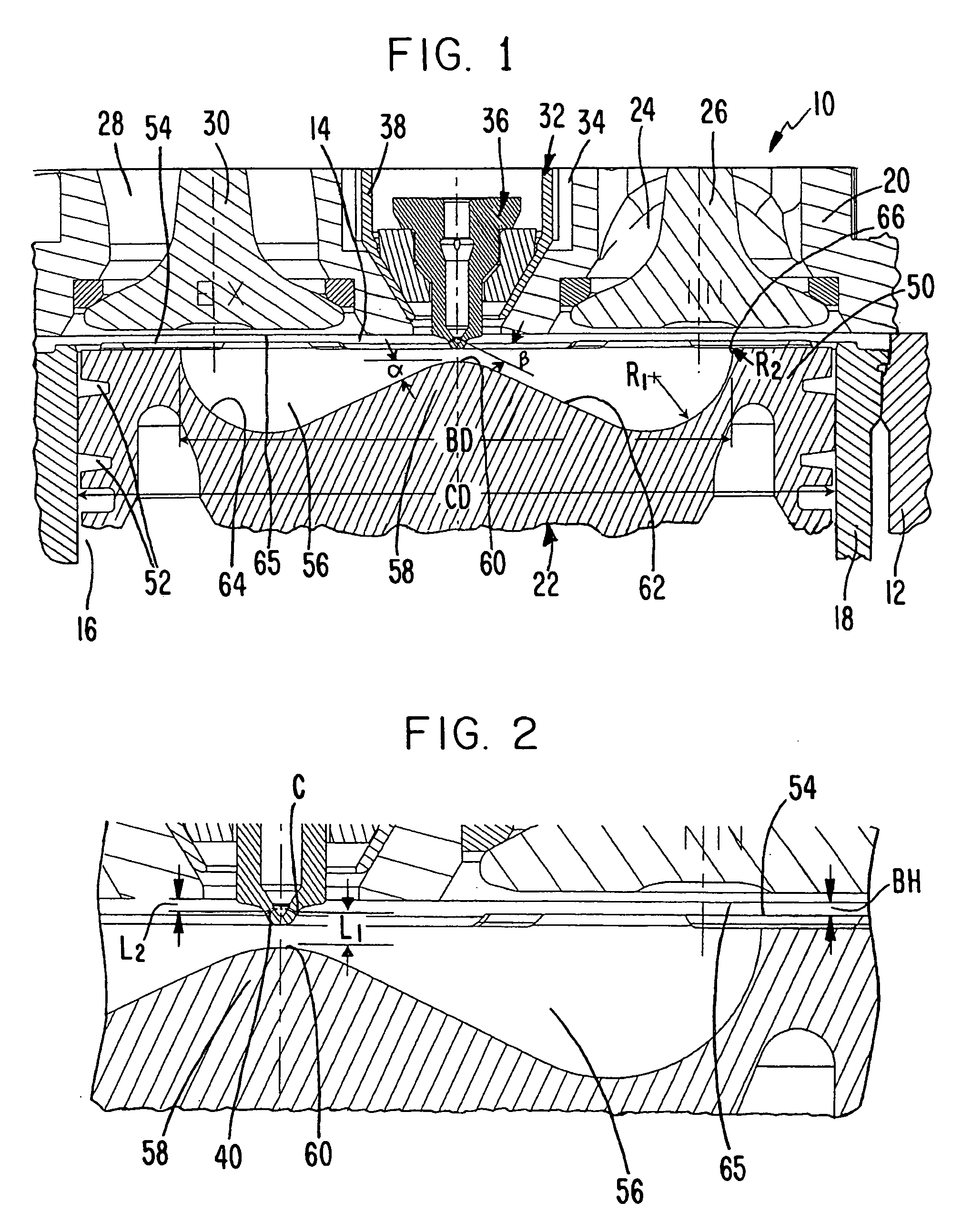
[0033] Referring to FIG. 1, the present invention is directed to an internal combustion engine, a portion of which is shown in a cutaway cross sectional view and generally indicated at 10, capable of producing emissions, e.g. NOx and particulates, at levels significantly lower than emissions levels produced by conventional engines and below recent government regulated limits. As discussed hereinbelow, engine 10 includes various precise configuration parameters resulting in a combustion process which achieves desired combustion characteristics for producing acceptably low emissions satisfactory to meet newly adopted engine operating standards applicable to diesel engines including both low noxious emissions and low particulates, while achieving desirable fuel economy and efficiency.

[0034] Engine 10 includes an engine block, only a small portion of which is illustrated at 12, and at least one combustion chamber 14. Of course, the engine may contain a plurality of combustion chambers,...


PUM


Abstract

An engine is provided which includes various precise configuration parameters, including dimensions, shape and/or relative positioning of the combustion chamber features, resulting in a combustion process minimizing NOx emissions and particulates. The combustion chamber includes one or more of the following: a spray angle relative to an inner bowl floor angle; a vertical distance from the tip of the piston bowl to the injection orifices; a number of injection orifices; a swirl ratio; a vertical distance from the injection orifices to an inner face of the cylinder head; a radius of curvature of an outer bowl section; chamfer with dimensional parameters; and a transition radius.

Description

[0001] This application is a continuation-in-part of application Ser. No. 10 / 814,332, filed Apr. 1, 2004, the contents of which are incorporated herein by reference, which is a continuation of application Ser. No. 10 / 166,051, filed Jun. 11, 2002, now Pat. No. 6,732,703.BACKGROUND OF THE INVENTION [0002] 1. Technical Field [0003] The invention relates to an improved engine capable of minimizing emissions. [0004] 2. Description of the Related Art [0005] Internal combustion engine designers continue to confront an ever more demanding set of governmentally mandated emissions standards and performance objectives. Modifications made to meet one standard may lead to increased emissions of a type that cause another standard to be exceeded. Thus designers are often confronted with not only the challenge of meeting a newly imposed emission standard but to do so in a way that does not cause other emissions standards, previously met or newly imposed, to be exceeded. The engine designers must al...

Claims


Application Information

Patent Timeline
IPC IPC(8): F02B3/00F02B31/00F02F3/26
CPCF02B23/0621F02B23/0651F02B23/0669F02B23/0672F02B23/0696F02M61/1846Y02T10/125Y02T10/12
Inventor STANTON, DONALD W.ZEHR, RANDALL L.ECKERLE, WAYNE A.NTONE, FRANCOIS
Owner CUMMINS INC
Why Eureka
Try Eureka