Reverse infrastructure location system and method

a reverse infrastructure and location technology, applied in the field of position determination, can solve the problems of high installation cost, inconvenient operation, and limited resolution, and achieve the effect of reducing the number of devices

Inactive Publication Date: 2006-04-06
SYMBOL TECH INC
View PDF22 Cites 164 Cited by
  • Summary
  • Abstract
  • Description
  • Claims
  • Application Information

AI Technical Summary

Benefits of technology

[0008] A method is provided for locating in real time a moveable terminal within a workspace containing an array of radio frequency identification (RFID) tags associated with the workspace infrastructure, preferably the light fixtures. The method comprises having the terminal send interrogation signal(s) to the fixed tags, receiving responses therefrom and determining the terminal location based on the known locations of the responding tags. In a proximity approach the terminal varies the transmit power and/or rec

Problems solved by technology

While this arrangement works, it suffers from a number of disadvantages well known in the art, as for example, complexity, high installation cost, limited resolution, undesirably high power drain for the mobile beacon transmitter, and so forth.
A further difficulty with this approach is that it is often very difficult to retrofit an existing structure or area to reliably use this approach since it is sensi

Method used


Image

  • Reverse infrastructure location system and method
  • Reverse infrastructure location system and method
  • Reverse infrastructure location system and method

Examples


Embodiment Construction

[0019] The following detailed description is merely exemplary in nature and is not intended to limit the invention or the application and uses of the invention. Furthermore, there is no intention to be bound by any expressed or implied theory presented in the preceding technical field, background, brief summary or the following detailed description.

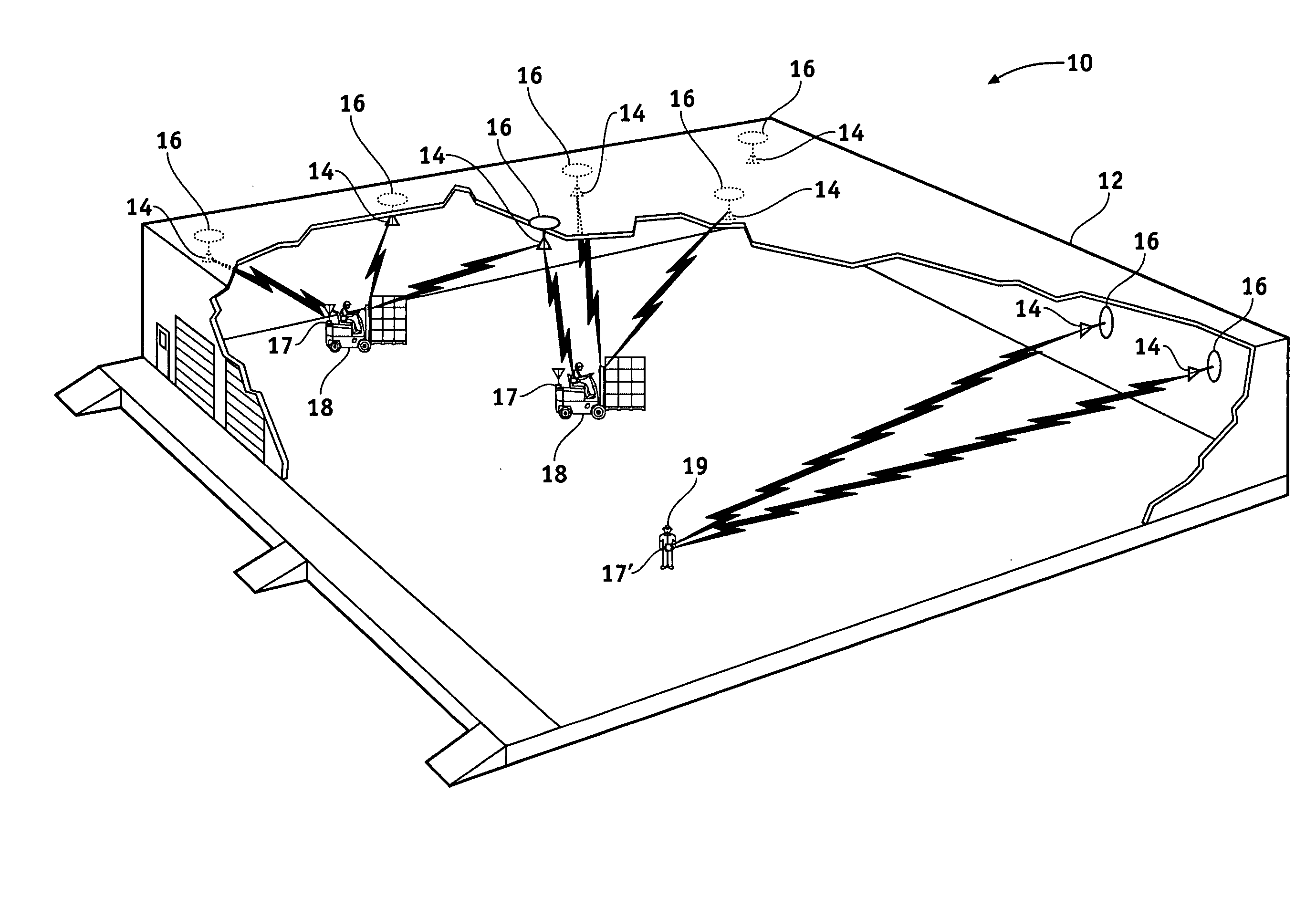
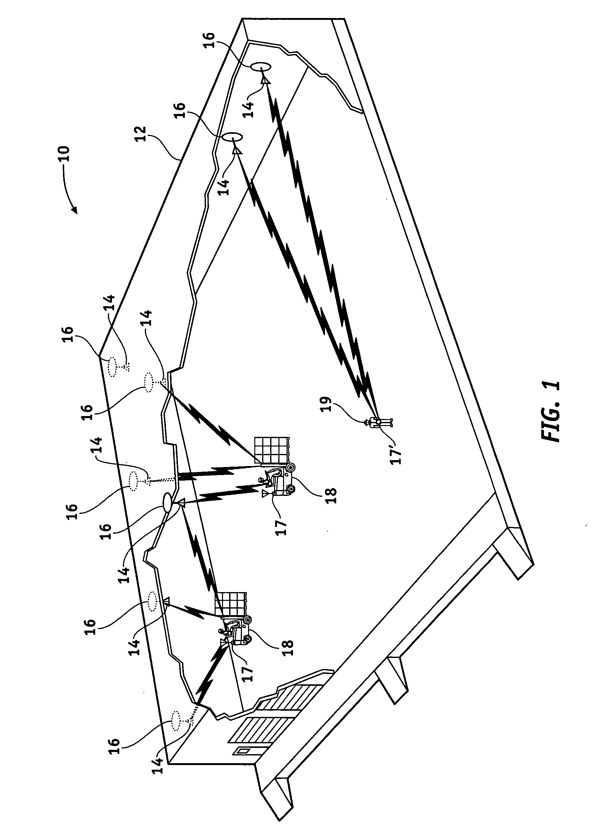
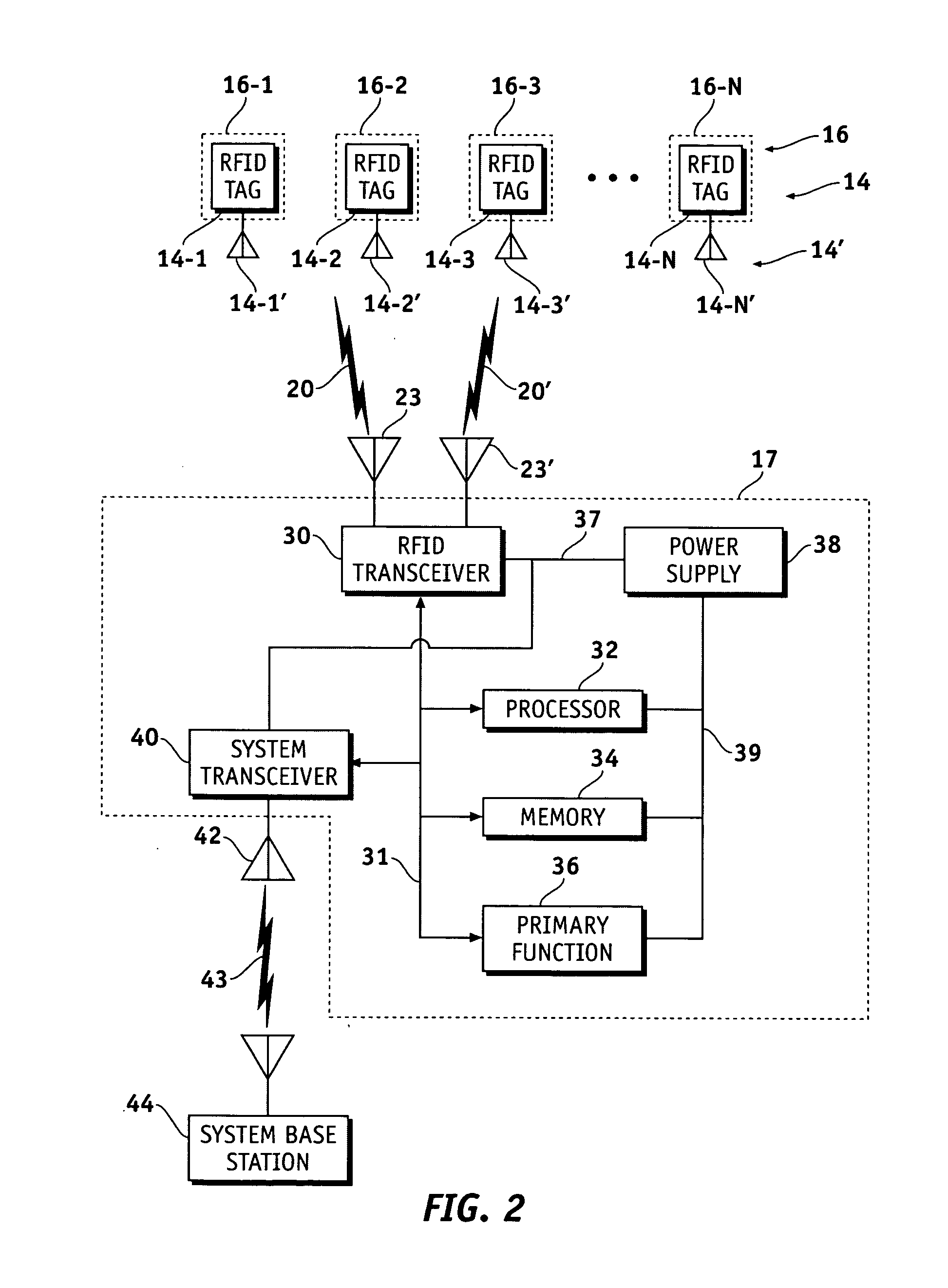
[0020] It has been found that many of the problems associated with prior art real time position locating systems can be avoided by using what can be referred to as “reverse RFID” or “reverse infrastructure” position location. In this arrangement, multiple RFID tags are provided in known locations within the work area, and the mobile terminal acts as a tag interrogator and / or reader to determine its position based on the known positions of the tags it interrogates. In the preferred embodiment, the tags are located in, on or in association with light fixtures since such infrastructure generally already exists in most buildings or areas of ...


PUM


Abstract

Methods and apparatus are provided to locate a terminal within a workspace. Radio frequency identification (RFID) tags are provided in known locations, preferably in, on or adjacent the light fixtures or other workspace infrastructure. The terminal comprises an RFID tag interrogation transceiver, processor and memory. The transceiver interrogates the tags which respond with information correlatable with their unique locations. The terminal determines its locations relative to the known locations of responding tags by, for example, varying its transmit power and/or receiver sensitivity and/or by trilateration using, for example, phase or time difference of arrival measurements on the tag response signals. Once it has determined its own location it may transmit or otherwise announce its location as desired by the user. In a preferred embodiment, the natural electromagnetic radiation and/or RADAR cross section backscatter from fluorescent type fixtures, modulated with their position information, acts as the RFID infrastructure beacon.

Description

TECHNICAL FIELD OF THE INVENTION [0001] The present invention generally relates to position location, and more particularly to determining the position of a mobile object in real time. BACKGROUND OF THE INVENTION [0002] There are many applications today where it is desired to determine the location of a moveable object. For example, there is often a need to locate a moveable person, forklift, pallet or other cargo carrier in a warehouse, storage depot, factory or other area. In the past this has often been accomplished by placing a radio frequency (RF) beacon on the moveable object and then providing multiple infrastructure receivers at known locations in the area that receive signals from the moveable object and through trilateration or other proximity detectors determine the location of the moveable object within the area. While this arrangement works, it suffers from a number of disadvantages well known in the art, as for example, complexity, high installation cost, limited resol...

Claims


Application Information

Patent Timeline
IPC IPC(8): G08B13/14G01S19/11
CPCG01S13/75G01S13/876G06K17/00G06K2017/0048G01S13/46G01S2013/466
Inventor DURON, MARK WILLIAMBRIDGELALL, RAJ
Owner SYMBOL TECH INC
Why Eureka
Try Eureka