Method for determining the image quality of an optical imaging system

a technology of optical imaging and image quality, applied in the direction of optical apparatus testing, optical radiation measurement, instruments, etc., can solve the problems of uneconomical and inaccurate determination of image quality for a plurality of field positions of imaging systems, uneconomical procedures, etc., to prevent edge cropping, improve image quality, and improve image quality

Inactive Publication Date: 2006-04-06
CARL ZEISS SMT GMBH
View PDF27 Cites 49 Cited by
  • Summary
  • Abstract
  • Description
  • Claims
  • Application Information

AI Technical Summary

Benefits of technology

[0031] cutting out relevant image portions, e.g., from axial points and field points, while preventing edge cropping.
[0032] These measures for improving image quality are particularly advantageous with respect to the accuracy that can be achieved with the additional method steps according to the invention.
[0033] After impr

Problems solved by technology

It is disadvantageous that this assessment must be considered only as integral information.
This procedure requires a relatively high technical complexity and is therefore very cost-intensive and not usually employed in connection with microscope manufacture.
In this connection, a continual problem, particularly for microscope producers, is the lack of an available general testing procedure that would make it possible to determine the image quality as accurately as possible for the di

Method used


Image

  • Method for determining the image quality of an optical imaging system
  • Method for determining the image quality of an optical imaging system
  • Method for determining the image quality of an optical imaging system

Examples


Embodiment Construction

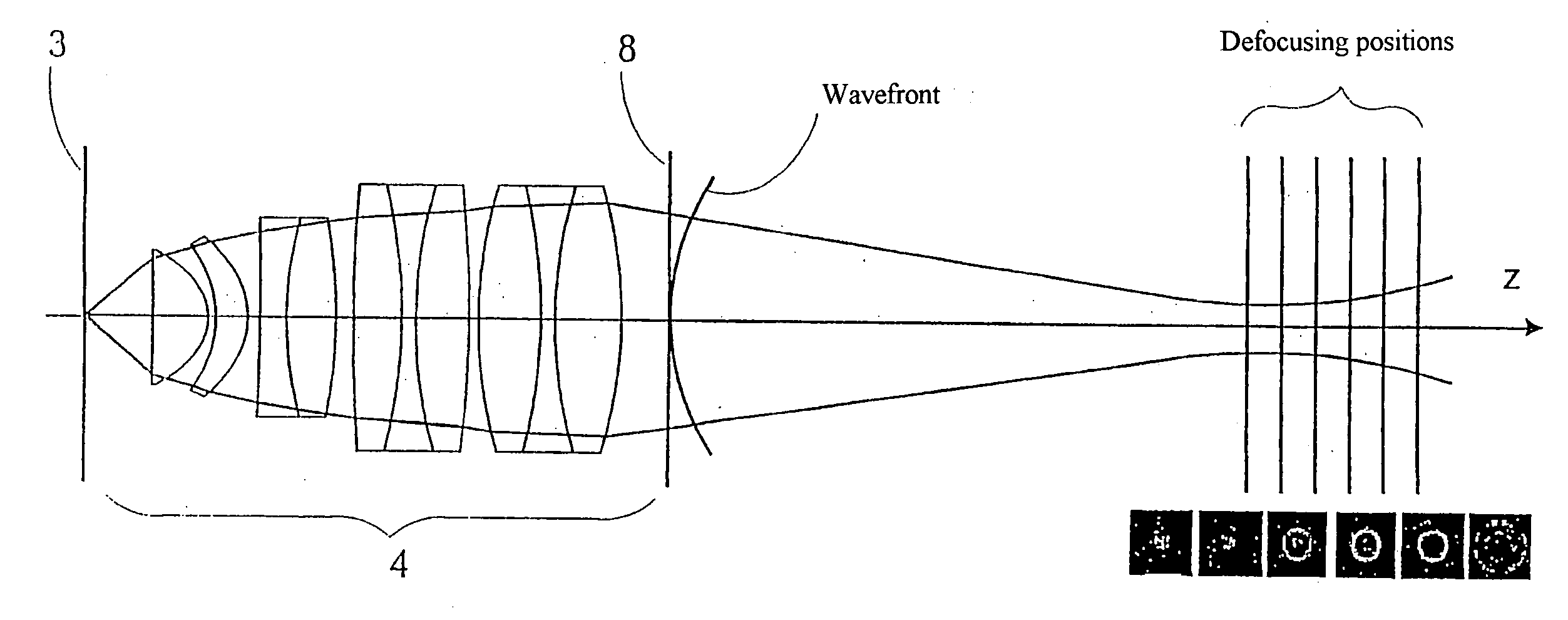
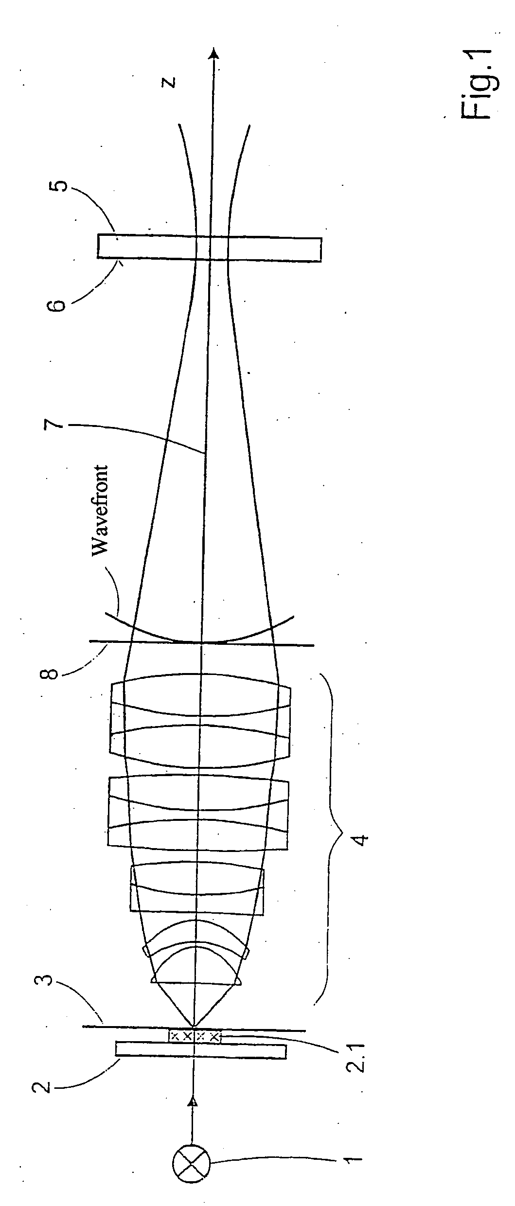
[0109] The subassemblies according to FIG. 1 substantially comprise an illumination device 1, a sample holder 2 with a sample 2.1 which is positioned in or near the object plane 3, an objective 4, and a CCD camera 5, as spatially resolving detection device, which is positioned in or near the image plane 6 of the objective 4. The subassemblies have a common optical axis 7 which does not necessarily extend in a straight line.

[0110] The subassemblies are adjusted relative to one another in a first method step in such a way that it is possible for the sample 2.1, which can exist physically or in the form of an image, to be projected onto the receiving surface of the CCD camera 5. The receiving surface of the CCD camera 5 comprises an array of sensor elements (pixels), and information concerning the intensity of the impinging illumination light influenced by the sample can be read off at the output thereof.

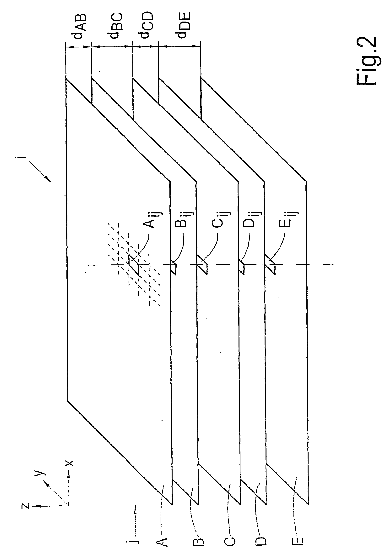
[0111] In a second method step, images are recorded from different defocusing ra...


PUM


Abstract

The invention is directed to a method for determining the image quality of an optical imaging system and to the use of the method according to the invention for determining the influence of samples on the amplitude distribution and phase front distribution of the illumination light, of which the amplitude distribution is known in particular. The invention comprises the following steps: adjusting the subassemblies relative to one another in such a way that it is possible to project images of a sample on the detection device; recording a plurality of images of the sample from different reference planes near the focus plane; improving the image quality by image processing, particularly to reduce noise, to compensate for local variations in sensitivity of the detection device, and to center the intensity centroids respectively on a predetermined location in the images; computational linking of the spatially resolved image information, of adjustment values and system variables relating to the optical imaging system, and of information concerning the sample with the aim of determining characteristic numbers that are characteristic of the wavefront deformation caused by the imaging system; and outputting the characteristic numbers and associating them with the imaging system for describing the image quality.

Description

CROSS-REFERENCE TO RELATED APPLICATION [0001] This application claims priority of International Application No. PCT / EP2004 / 006302, filed Jun. 11, 2004 and German Application No. 103 27 019.1, filed Jun. 12, 2003, the complete disclosures of which are hereby incorporated by reference.BACKGROUND OF THE INVENTION [0002] a) Field of the Invention [0003] The invention is directed to a method for determining the image quality of an optical imaging system substantially comprising an illumination device, a sample holder with sample, imaging optics, and at least one spatially resolving detection device. The invention is further directed to the use of the method according to the invention for determining the influence of samples on the amplitude distribution and phase front distribution of the illumination light, of which, in particular, the amplitude distribution is known. [0004] b) Description of the Related Art [0005] In connection with the manufacture of high-quality imaging optics, parti...

Claims


Application Information

Patent Timeline
IPC IPC(8): G01B9/00G01M11/02
CPCG01M11/0257
Inventor ENGEL, THOMASGROSS, HERBERT
Owner CARL ZEISS SMT GMBH
Why Eureka
Try Eureka