
Multi-processor system

a multi-processor and memory type technology, applied in the field of shared memory type multi-processor systems, can solve the problems of difficult high-speed transmission of signals, difficult control of coherence, and obstacle to solving problems, and achieve the effect of shortening the time, increasing the speed of transmission and reception of updated data

Inactive Publication Date: 2006-04-06
FUJITSU LTD
View PDF7 Cites 31 Cited by
  • Summary
  • Abstract
  • Description
  • Claims
  • Application Information

AI Technical Summary

Benefits of technology

The present invention is a multi-processor system that improves performance by minimizing factors that decrease performance, such as controlling coherency. The system includes a dedicated line unit for updating data in a shared memory area and a global bus unit for transmitting data update notifications while arbitrating access to the shared memory. The system ensures that each processor and the shared memory have exclusive access to the shared memory area, thereby securing coherency. The invention also increases the speed of data transmission and reception by providing a dedicated line unit for exclusive data transmission and reception.

Problems solved by technology

The former is ascribed to the fact that it is difficult to transmit the signals at high speed because of the electrical conditions when the signal transmission distance in the global bus becomes long, and a plurality of processors share the same signal line.
As a result, these restrictions give rise to the following problems to the access to the shared memory space.
This control of coherency is also an obstacle for solving the above-mentioned problems, the reasons for which will be described later.
Therefore, to satisfy Requirement 1 for the control of coherency means that Requirement 2 which arises in using the global bus is imposed in the same way, thereby causing an obstacle for solving the problems.
As seen from these examples, since conditions are attached to the timing of various operations, the control of coherency creates a sort of restriction in itself when an effort is made to shorten the processing time and to improve the performance of the system.

Method used


Image

  • Multi-processor system
  • Multi-processor system
  • Multi-processor system

Examples


first embodiment

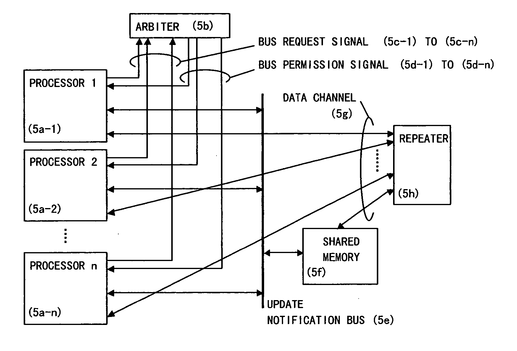
[0069] Described below is the principle of the present invention in the present invention. In FIG. 5, the part which corresponds to the global bus in a conventional example is an update notification bus (5e), which is used as a bus for exclusively performing a data update notification and a transmission request of updated data. The contents of the updated data are transmitted and received using a data channel (5g) between the update notification bus (5e) and a repeater (5h). The data channel is assumed to be a high-speed broadband transmission means which is already known of (for example, Gigabit Ethernet). The repeater (5h) has a function for transmitting data which appears on each port to which the data channel is connected to all the ports. If the number of processors is small, and a realistic number of data channels suffice, data channels can be provided in 1:1 between all the processors and the shared memory without providing a repeater, and the processing of transmitted data f...

second embodiment

[0078]FIG. 7 shows an example of a time chart of the processing based on the present invention.

[0079] In FIG. 7, data update is performed every four addresses. The update notification which processor 1 and processor 2 transmit is transmitted by indicating the top of the address to be updated, and updated data of the corresponding address is transmitted as a block of data.

[0080] If a data update is performed with a fixed data length, data updates including a group of data which are not required because of software processing must sometimes be performed, so that there is a possibility that the data channel and the bandwidth of the shared memory cache are wasted and the effective bandwidth is reduced. Thus, the system is configured so that the updated data size may be variable and only necessary and sufficient data may be transmitted to the data channel.

[0081]FIG. 8 shows an example of a time chart when data update is performed in differing data sizes. In FIG. 8, the difference from ...

third embodiment

[0083] The principle of the present invention is that a processor makes it possible to select the attribute of whether the control of coherency is necessary or not in every write access, does not issue an update notification of write accesses for which the attribute of the control of coherency is designated as not necessary, and controls transmitting only updated data to the other processors. There are some uses of the shared memory space for which the guarantee of coherency is not required according to the processing contents of software. Thus in this embodiment software uses this control for such processing, decreases the frequency of using an update notification bus, improves the bandwidth of the shared memory space, shortens the time in which updated data is reflected to the other processors, and restrains the increase of latency due to the occurrence of unnecessary access competition to a necessary minimum to decrease the average latency of read accesses.

[0084]FIG. 9 shows an e...


PUM


Abstract

Data transmission for writing data into a shared memory is performed by a high-speed dedicated line provided between each processor and the shared memory. When a processor performs writing to a shared memory space, the processor notifies an update notification bus corresponding to the conventional global bus, to which address the update is to be performed. The other processors which have detected this notification inhibit access to that address and wait for the write data to be sent to the address via the dedicated line. When the data has arrived, the data is written into the corresponding address. Here, the data is also written into the corresponding address, thereby maintaining the cache coherency. Moreover, when transmitting a write address, it is necessary to acquire the bus use right while data transmission is performed by using the dedicated line, which significantly reduces the time required for acquiring the bus use right.

Description

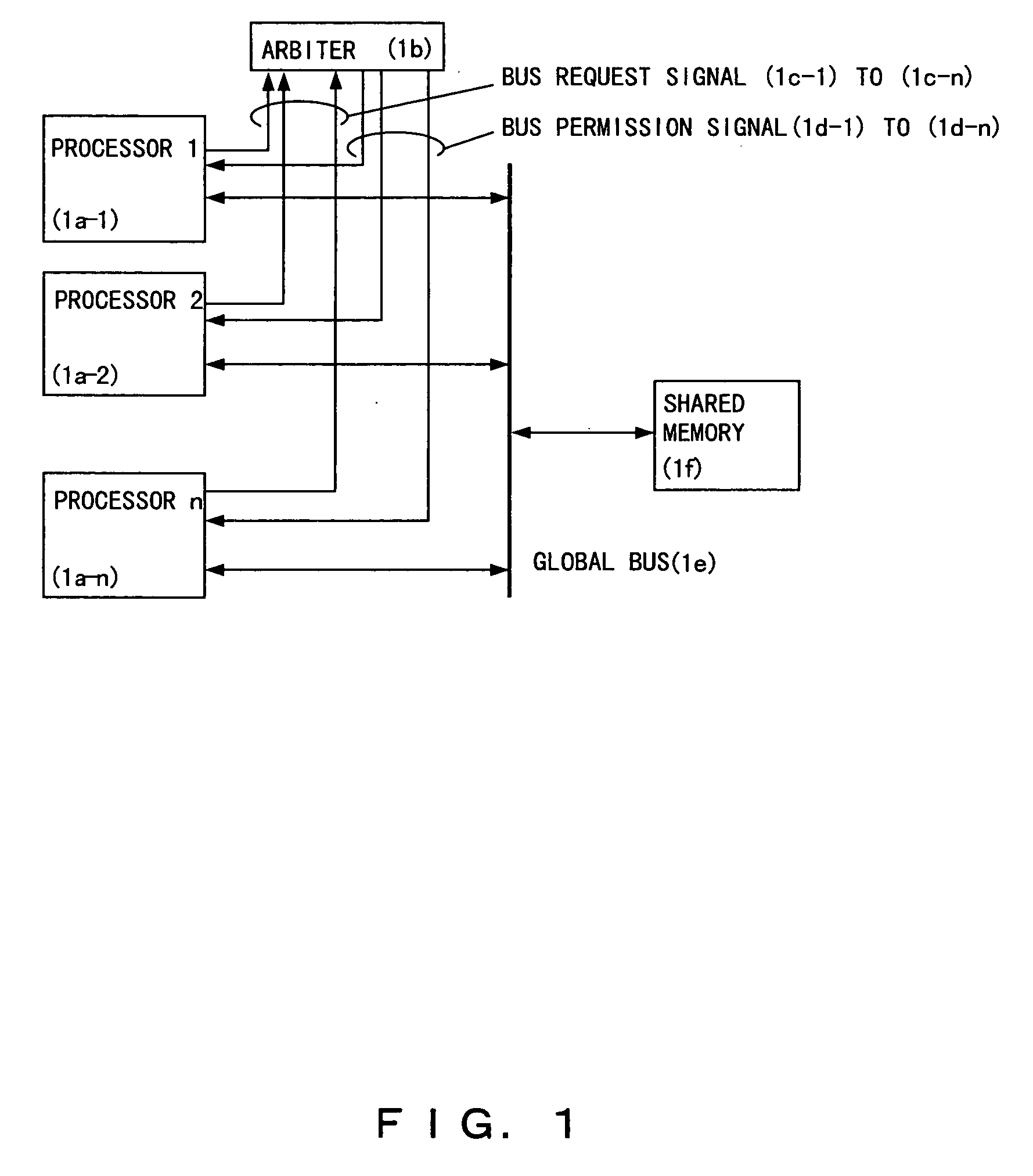
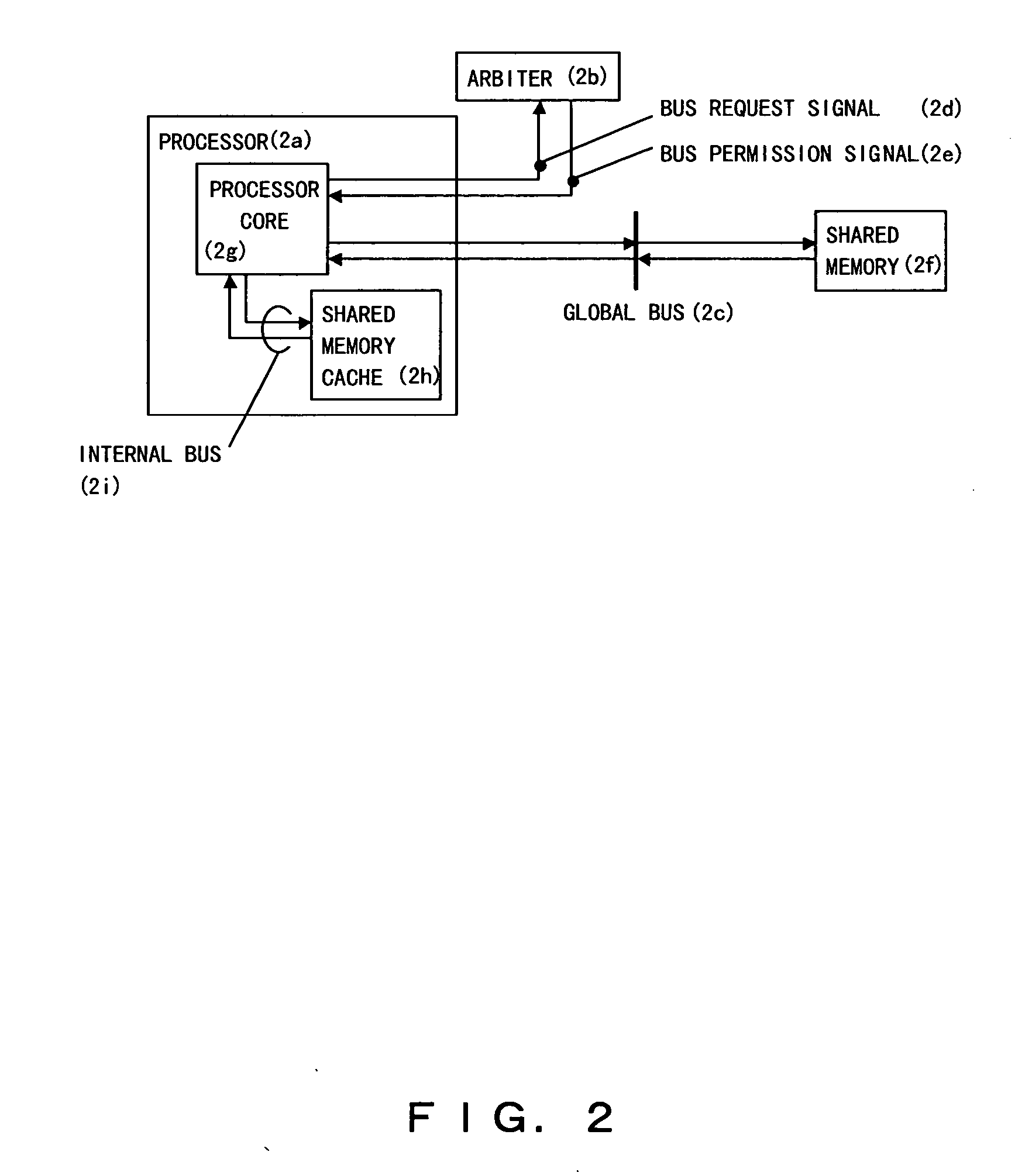
CROSS REFERENCE TO RELATED APPLICATION [0001] This application is a continuation of international PCT application No. PCT / JP2003 / 006868 filed on May 30, 2003.BACKGROUND OF THE INVENTION [0002] 1. Field of the Invention [0003] The present invention relates to a shared memory type multi-processor system in which a plurality of processors are connected and a shared memory space shared by the processors is arranged, and more specifically to a system comprising processors having a shared memory cache for caching data in the shared memory space. Processing of software is performed by each individual processor, and the shared memory is used as the space for transferring data when the processing is handed over between processors and for storing information which should be managed not by standalone processors but by a system. The shared memory cache is introduced to improve the performance of the system by speeding up access to the shared memory. [0004] 2. Description of the Related Art [000...

Claims


Application Information

Patent Timeline
Patent Type & Authority Applications(United States)
IPC IPC(8): G06F12/00G06F12/08G06F13/16
CPCG06F12/0813G06F12/0831G06F13/1663
Inventor SHIMADA, TAKESHINAKAGAKI, TATSURUKOBAYASHI, AKIHIRO
Owner FUJITSU LTD
Learn More