Device for longitudinal cutting of a continuous web material, such as corrugated cardboard

a technology of web material and longitudinal cutting, which is applied in the direction of metal working equipment, shearing machines, shearing apparatus, etc., can solve the problems of extreme precision in the adjustment of the distance between the cutting edges of the blades and the edge of the counter-blade, rapid wear of the plastic in the channel, and the need to reduce the risk of damage to the material. , to achieve the effect of simplifying the structur

Inactive Publication Date: 2006-04-13
FOSBER
View PDF78 Cites 11 Cited by
  • Summary
  • Abstract
  • Description
  • Claims
  • Application Information

AI Technical Summary

Benefits of technology

[0012] The object of the present invention is to produce a cutting device and in particular a cutting device for slitter-scorer machines destined to process corrugated cardboard or analogous continuous web products, which has a simplified structure with respect to known devices. In particular, the object of a preferred embodiment of the invention is to produce a device which makes it possible to eliminate the need for an autonomous positioning system of the counter-blades, totally or partly overcoming the drawbacks of conventional devices.
[0014] The counter-blade with which the intermediate blades cooperate is fixed, in the sense that the transverse position thereof does not require adjustment when the position of the cutting blades is changed.
[0015] In this way it is possible to radically simplify the positioning mechanisms of the blades and counter-blades, providing a single manipulator or robot only on one side of the path of the web material. This is due to the fact that the intermediate disk-shaped blades cooperate with a fixed counter-blade, while the lateral counter-blades, movable transversely and destined to cut the trimmings of the web materials, can be easily positioned,,for example using the same manipulator or robot which performs positioning of the blades, by means of a lateral mechanical connection, external to the edges of the web material.
[0016] For this purpose, each of the movable lateral counter-blades may advantageously be connected to the respective lateral blade and movable jointly therewith to be positioned together with the blade transversely to the direction of feed of the web material. An arrangement of this type obtains the further advantage of maintaining the correct reciprocal position between the lateral blade and corresponding counter-blade at all times, without the danger of misalignment caused by incorrect positioning of either of the two.
[0019] In a possible embodiment, each lateral blade and each intermediate blade is carried by a respective slide movable along a transverse guide, to be positioned each time an order is changed. Preferably, each of the movable counter-blades is carried by a shoe sliding transversely to the direction of feed of the web material, on the same guides on which the slides carrying the blades slide, although it would also be possible to use separate guides. Advantageously, the shoe of each movable counter-blade can also be connected to the slide carrying the corresponding lateral blade, for example with a mechanical connection which allows adjustment of the relative distance between shoe and slide.

Problems solved by technology

This construction makes it unnecessary to produce counter-blades which must be positioned at each order change, but does not solve the problem of frequent order changes, as repositioning of the cutting blades in positions which differ from order to order causes rapid wear of the plastic in which the channels forming the counter-blades are cut.
This is particularly true in the lateral areas in which the trimmings are cut, as the cutting lines of the trimmings in the different work orders are very close to one another, which leads to rapid wear of the plastic.
This system has drawbacks as the distance between the cutting edges of the blades and the edge of the counter-blade must be adjusted with extreme precision.

Method used


Image

  • Device for longitudinal cutting of a continuous web material, such as corrugated cardboard
  • Device for longitudinal cutting of a continuous web material, such as corrugated cardboard
  • Device for longitudinal cutting of a continuous web material, such as corrugated cardboard

Examples


Embodiment Construction

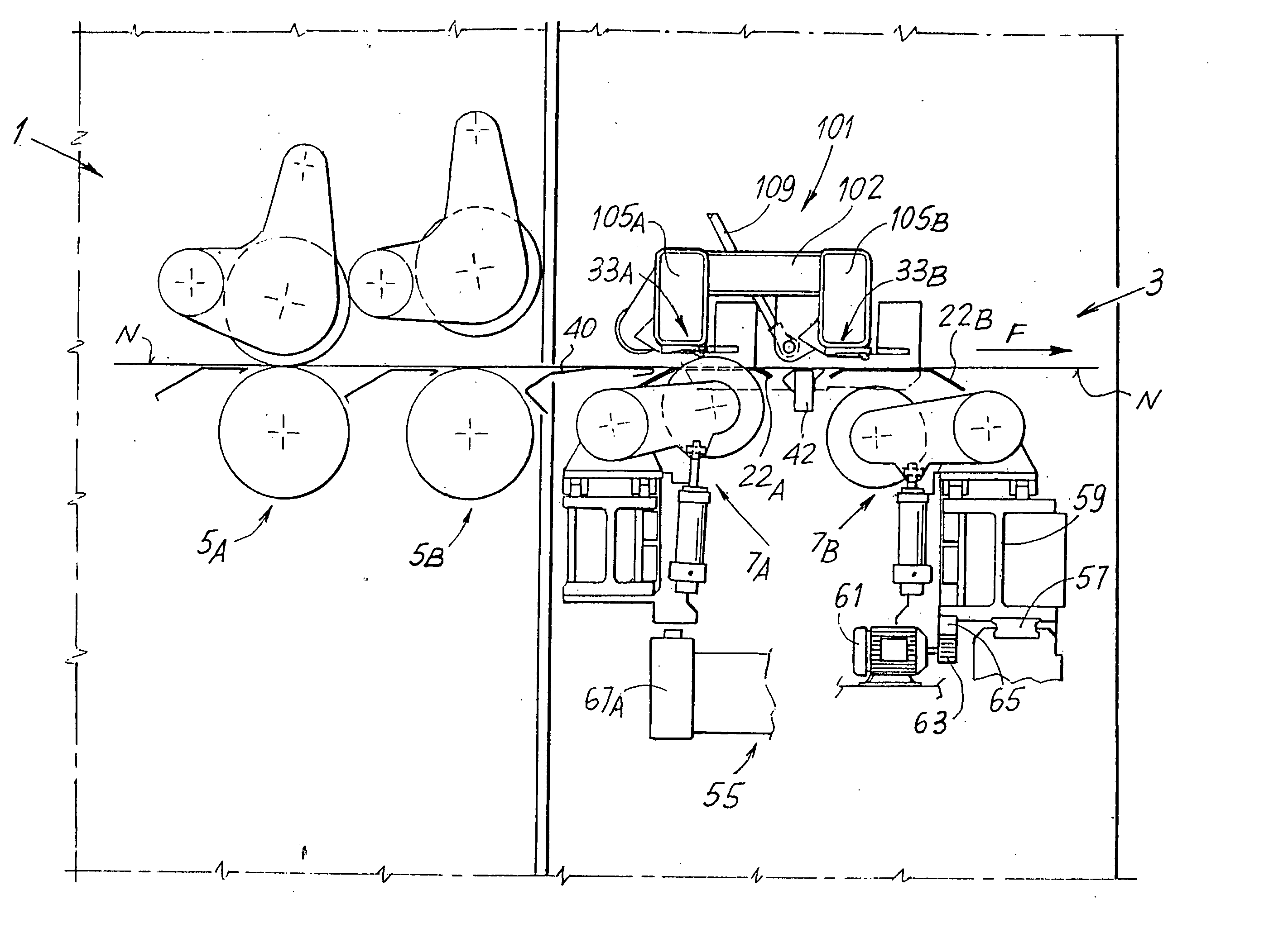
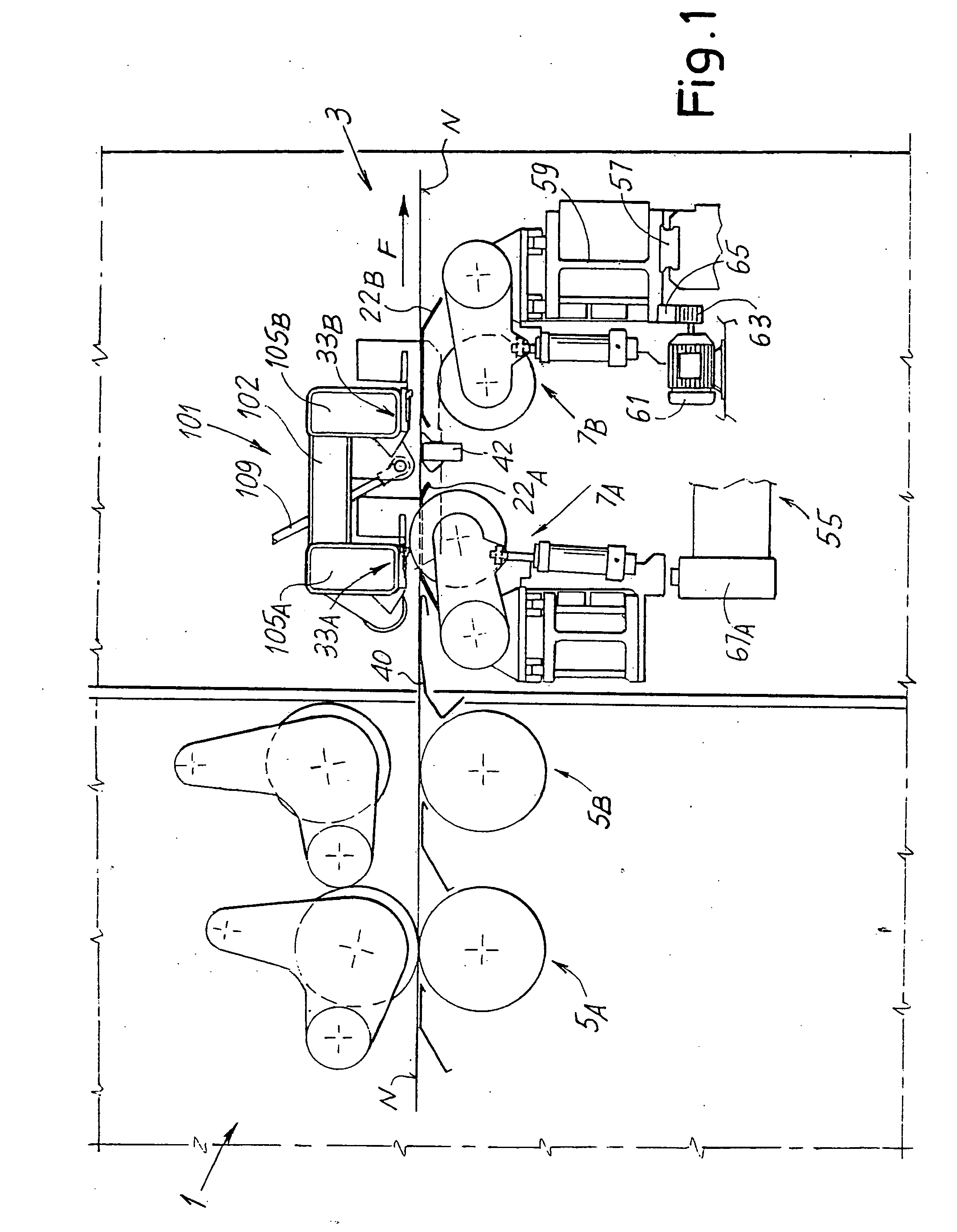
[0030] The accompanying drawing shows an application of the invention to a double slitter-scorer machine, but it must be understood that the principles on which the invention is based can also be applied to machines of a different type, such as machines with a single cutting unit instead of two cutting units which operate alternately, or to machines with no scoring station, or even in more complex machines with a greater number of scoring and slitting stations.

[0031]FIG. 1 schematically shows a lateral view of the slitter-scorer machine, in which the number 1 schematically indicates the scoring section and the number 3 the slitting section. The scoring section comprises a first series of scoring tools 5A and a second series of scoring tools 5B. In the layout shown in FIG. 1 the scoring tools 5A are in the operating condition and act on the web material N, typically a corrugated cardboard web. The scoring tools 5B are in the inoperative position, that is, they do not act on the web ...


PUM

PropertyMeasurementUnit
Currentaaaaaaaaaa
Currentaaaaaaaaaa
Currentaaaaaaaaaa

Abstract

The device comprises a path for the web material (N) and, along said path, at least one cutting unit (7A). The cutting unit comprises: a plurality of intermediate disk-shaped blades (9A) disposed on one side of the feed path of the material, which can be positioned transversely to the direction of feed and cooperating with a fixed counter-blade (33A) disposed on the opposite side of said path. Also provided are two lateral disk-shaped blades (10A) to cut the trimmings; and a member for transverse positioning of the blades. The two lateral blades each cooperate with a respective movable counter-blade (71A), separate from the fixed counter-blade, which can be positioned transversely to the direction of feed of the web material.

Description

TECHNICAL FIELD [0001] The present invention relates to a device for longitudinal cutting of a continuous web material, such as, although not exclusively, a corrugated cardboard. The invention also relates to a slitter-scorer machine, which comprises a cutting device to perform slitting and scoring of a corrugated cardboard or another continuous web material. STATE OF THE ART [0002] In the production of corrugated cardboard articles, such as cardboard boxes, a web of corrugated cardboard fed continuously is divided longitudinally by means of cutting blades into a plurality of strips of various widths and each strip is scored according to scoring lines disposed variably along the transverse extension of the strips of cardboard. Besides cutting the cardboard web into individual strips, the cutting blades trim the web, that is, they eliminate two thin strips of web material along the longitudinal edges, called trimmings. The strips of cardboard are then cut transversely to produce indi...

Claims


Application Information

Patent Timeline
IPC IPC(8): B23D19/00B26D1/14
CPCB26D1/205B26D1/225B26D7/2635B26D2007/0068Y10T83/7822Y10T83/7863Y10T83/9309Y10T83/768
Inventor ADAMI, MAURO
Owner FOSBER
Why Eureka
Try Eureka