Hologram recording apparatus and hologram recording method

a hologram and recording method technology, applied in the field of hologram recording methods, optical recording mediums, hologram recording devices, etc., can solve the problems of forming undesired diffraction gratings, diminishing the and reducing the forgery prevention effect of hologram seals day by day, so as to reduce the risk of forgery or alteration, the apparatus configuration is simple and the effect of reducing the risk of forger

Inactive Publication Date: 2006-04-13
FUJIFILM BUSINESS INNOVATION CORP
View PDF2 Cites 7 Cited by
  • Summary
  • Abstract
  • Description
  • Claims
  • Application Information

AI Technical Summary

Benefits of technology

[0025] As described above, the invention produces an effect such that a volume hologram being less susceptible to forgery or alteration, and having a superior finish can be recorded on demand with a simple apparatus configuration.

Problems solved by technology

Forgery and alteration of ID and credit cards and the like have been emerging as a serious social problem recently.
As a result, the forgery preventing effect of hologram seals is diminishing day by day.
However, the on-demand holograms, which employ a hologram transfer foil ribbon, have the following problems: it is possible for an outsider to duplicate a similar hologram by using a hologram not printed on a display medium but remained on the transfer foil ribbon (thus it is necessary to put the transfer foil ribbon after use under strict control for prevention of forgery); and as the transfer foil ribbon is a relief hologram, it is possible to forge the hologram by examining the surface relief structure thereof.
According to this method, reference beam is irradiated alone onto areas where the pattern of the signal beam is absent, thereby forming an undesired diffraction grating from multiple interference or the like due to the layer structure constituting the hologram recording medium.
This undesired diffraction grating creates undesired diffracted light which deteriorates the finish of the reproduced image, causing problems.

Method used


Image

  • Hologram recording apparatus and hologram recording method
  • Hologram recording apparatus and hologram recording method
  • Hologram recording apparatus and hologram recording method

Examples


first embodiment

(First Embodiment)

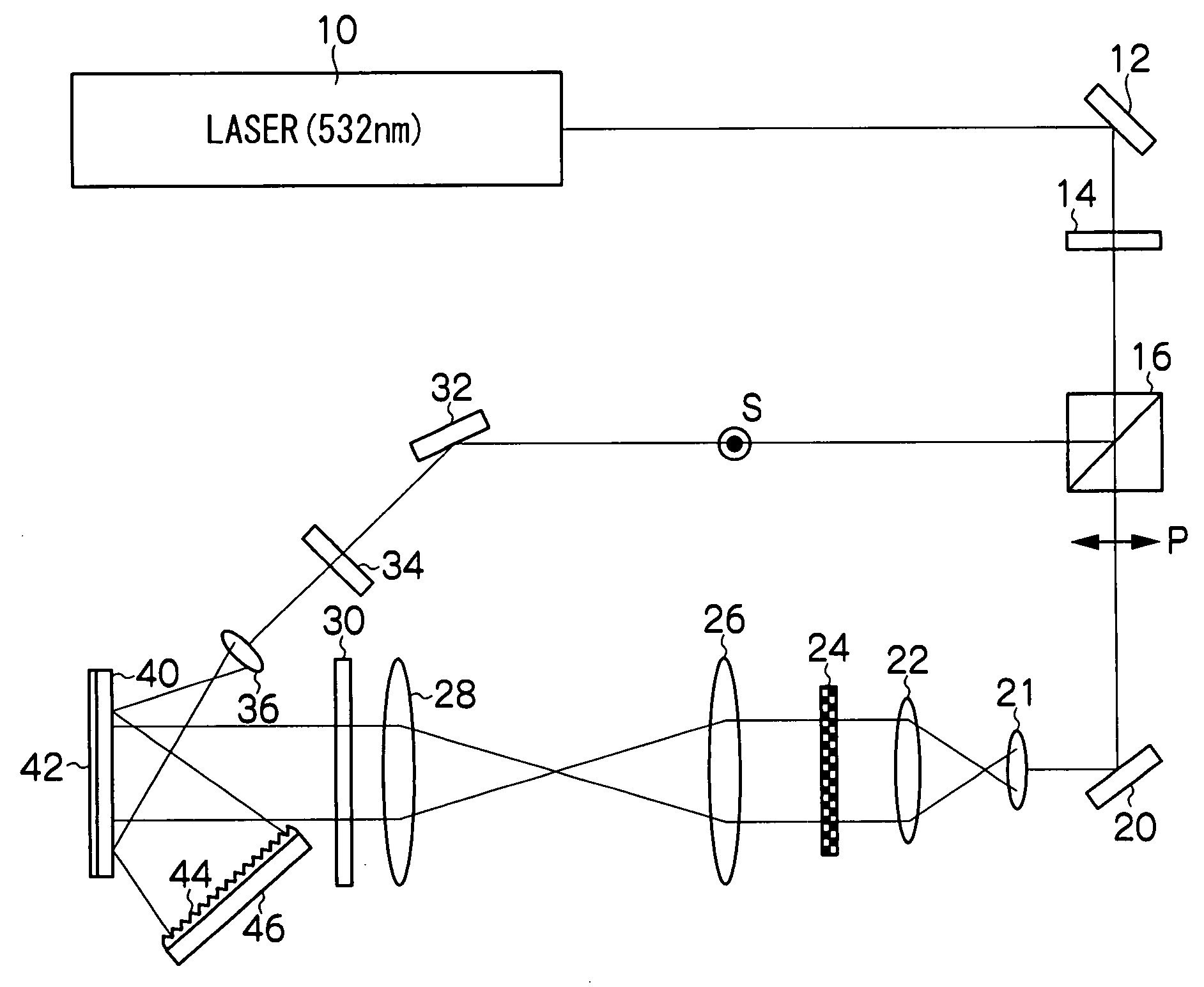
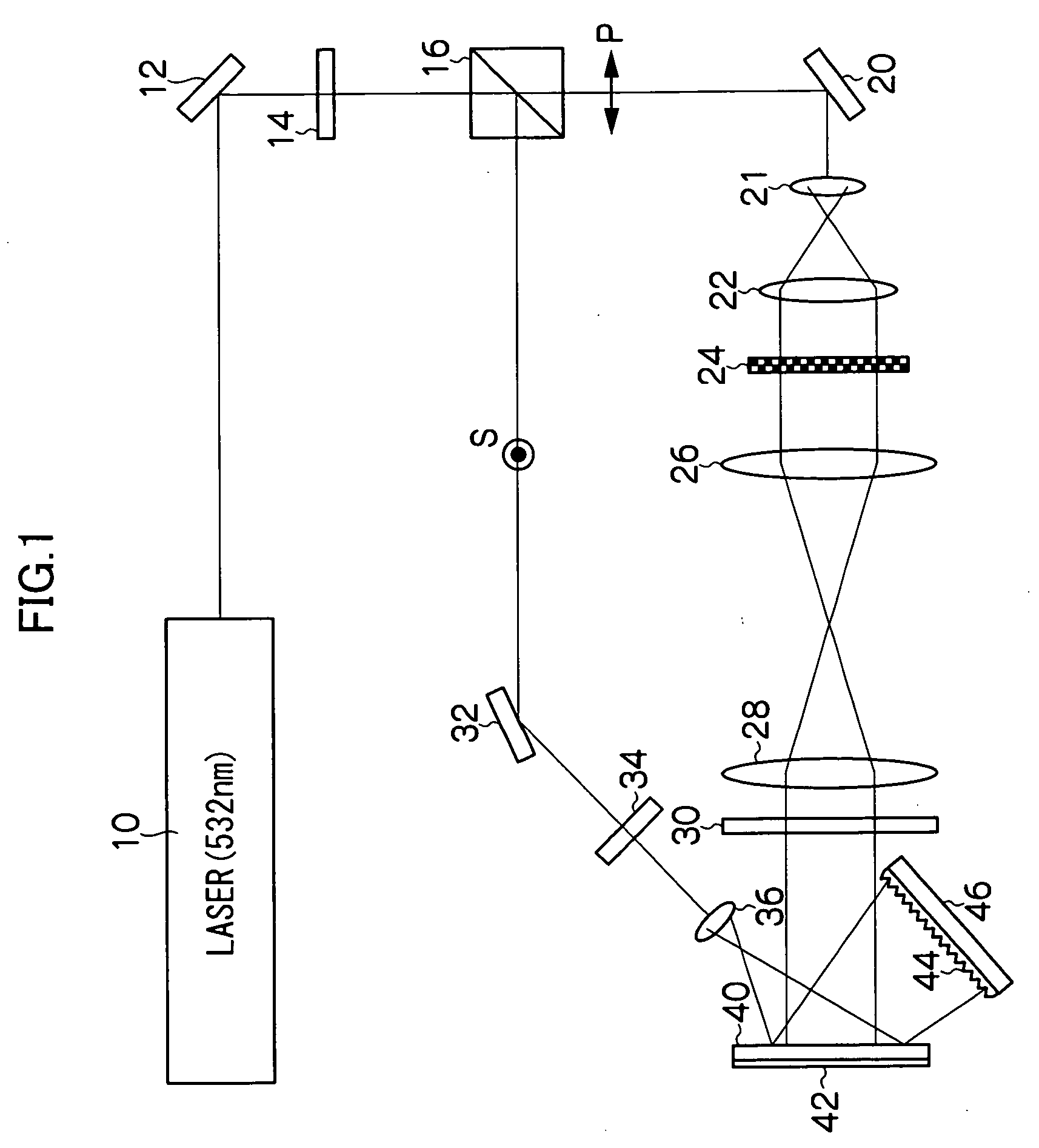
[0034] Referring to FIG. 1, a hologram recording apparatus according to the present embodiment includes a laser light source 10. From this laser light source 10, laser light of wavelength 532 nm being a coherent beam is emitted and irradiated.

[0035] On the laser light irradiation side of laser light source 10, there are a reflecting mirror 12 that reflects the laser light to change the optical path thereof, a half waveplate 14 that rotates the polarization plane of the linear polarized light reflected by reflecting mirror 12, and a polarizing beam splitter 16 that separates the laser light into two beams, i.e. light for the reference beam and light for the signal beam, by transmitting the P polarized light and reflecting the S polarized light, these components being arranged in this order. The half waveplate 14 is used for adjusting the intensity ratio of the signal beam and the reference beam.

[0036] On the light transmission side of the polarizing beam splitter ...

second embodiment

(Second Embodiment)

[0059] Referring to FIG. 3, a hologram recording apparatus according to the present embodiment is not provided with the reflecting mirror 42 for mounting the hologram recording medium 40, and the hologram recording medium 40 is supported by a support (not illustrated). Further, the diffusing plate 44 and the reflecting mirror 46 are disposed on the reference beam transmission side of the hologram recording medium 40.

[0060] Except for the above, the hologram recording apparatus according to the present embodiment has the same configuration as the hologram recording apparatus according to the first embodiment shown in FIG. 1, so that the description of the same configuration will be omitted and the same constituent elements will be denoted with the same reference numerals.

[0061] In this hologram recording apparatus, the circular polarized light that has passed through hologram recording medium 40 is diffused by diffusing plate 44. The diffused light diffused by di...

third embodiment

(Third Embodiment)

[0063] Referring to FIG. 4, a hologram recording apparatus according to the present embodiment is not provided with the reflecting mirror 42 for mounting the hologram recording medium 40, and the hologram recording medium 40 is supported by a support (not illustrated). The reflecting mirror 32, quarter waveplate 34, and the object lens 36 are each disposed so that the signal beam and the reference beam will respectively be irradiated onto the hologram recording medium 40 from different sides. Further, the diffusing plate 44 and the reflecting mirror 46 are disposed on the reference beam transmission side of the hologram recording medium 40.

[0064] Except for the above, the hologram recording apparatus according to the present embodiment has the same configuration as the hologram recording apparatus according to the first embodiment shown in FIG. 1, so that the description of the same configuration will be omitted and the same constituent elements will be denoted wi...


PUM

PropertyMeasurementUnit
wavelengthaaaaaaaaaa
reflection angleaaaaaaaaaa
thicknessaaaaaaaaaa

Abstract

A hologram recording apparatus includes a light source for irradiating coherent light, light separator for separating the coherent light into light for reference beam and light for signal beam, optical path changer for changing an optical path of each light separated by the light separator so that the reference beam and the signal beam may be irradiated simultaneously onto an optical recording medium, a spatial light modulator disposed in the optical path of the light for the signal beam for modulating the light for the signal beam in accordance with a supplied recording signal to create signal beam for recording a hologram, and diffused light irradiator for irradiating diffused light simultaneously with the reference beam at least onto an area of the optical recording medium where the reference beam is irradiated.

Description

CROSS-REFERENCE TO RELATED APPLICATION [0001] This application claims priority under 35 USC 119 from Japanese Patent Application No. 2004-264324, the disclosure of which is incorporated by reference herein. BACKGROUND OF THE INVENTION [0002] 1. Field of the Invention [0003] The present invention relates to a hologram-recording method, an optical recording medium, and a hologram-recording device, and in particular to a hologram-recording method for recording a volume hologram in an optical recording medium, and an optical recording medium and a hologram-recording device favorably used in the recording method. [0004] 2. Description of the Related Art [0005] Forgery and alteration of ID and credit cards and the like have been emerging as a serious social problem recently. One of the reasons for that is the progress in copying technology, which enables duplication of the hologram seals adhered for prevention of forgery. [0006] Conventional hologram seals, which are duplicated from a mas...

Claims


Application Information

Patent Timeline
Patent Type & Authority Applications(United States)
IPC IPC(8): G11B7/00
CPCG03H1/0011G03H1/0402G03H1/0486G03H1/28G03H2001/0413G03H2001/0415G03H2210/22G03H2210/54G03H2223/14G03H2250/42G03H2260/12G11B7/0065
Inventor YASUDA, SHINMINABE, JIROOGASAWARA, YASUHIROHAYASHI, KAZUHIROYOSHIZAWA, HISAEHAGA, KOICHIKAWANO, KATSUNORI
Owner FUJIFILM BUSINESS INNOVATION CORP
Why Eureka
Try Eureka