
Communication system, transmission station, and reception station

a communication system and transmission station technology, applied in the field of transmission stations, can solve the problems of large amount of power consumption, long processing delay, and large amount of processing at the rrc layer, and achieve the effect of reducing control delay to a mobile station withou, increasing processing delay and complexity of the devi

Inactive Publication Date: 2006-04-13
MITSUBISHI ELECTRIC CORP
View PDF4 Cites 50 Cited by
  • Summary
  • Abstract
  • Description
  • Claims
  • Application Information

AI Technical Summary

Benefits of technology

The present invention aims to solve problems such as control delay in mobile stations by reducing processing delay and complexity of devices. The invention includes a communication system with a transmitting station and a receiving station, which communicate through an HS-SCCH and an HS-PDSCH. The transmitting station transmits control information for controlling the receiving station without going through a process by the RRC layer process section, and the receiving station performs a prescribed process based on the control information without going through a process by the RRC layer process section. This reduces control delay to the receiving station without increasing processing delay and complexity of the device.

Problems solved by technology

In such ways, conventional communication systems need to increase the receiving ability of the mobile station when packet data is not transmitted and received, which results in a large amount of power consumption.
However, the process at the RRC layer requires relatively long time (approximately 100 ms).
Besides, the process at the RRC layer must be performed in both the base station and the mobile station, which actually takes processing time twice as long, and results in long processing delay.
On the other hand, an increase of the processing abilities of the RRC layers in order to shorten the processing delay carries with it increases in complexity of the device and the circuit scale, both in the base station and the mobile station.
Likewise, because a quick change to an optimum amount of offset in accordance with a propagation environment cannot be made with regard to the amount of HS-DPCCH power offset (Δ HS-DPCCH), transmission may be made with redundant power so that interference is increased thus decreasing transmission capacity and throughput, or conversely, transmission may be made with insufficient power so that the ACK / NACK fails to reach the base station thus increasing the number of data retransmissions.
In such ways, by transmitting all kinds of mobile-station-control information sent from an upper protocol layer than the MAC layer in the base station through the RRC layer process in the base station or the mobile station, control delay becomes longer, which in turn hampers the optimization of mobile station control, improvement in throughput, reduction of power consumption, and so on.

Method used


Image

  • Communication system, transmission station, and reception station
  • Communication system, transmission station, and reception station
  • Communication system, transmission station, and reception station

Examples


Embodiment Construction

[0137] Preferred embodiments of the present invention will be explained below, taking a case as an example where control information for controlling a mobile station by a base station is control information on the number of to-be-received HS-SCCHs.

1. FIRST PREFERRED EMBODIMENT

[0138] A communication system according to a first preferred embodiment of the present invention will be explained below. The term “channel” used in the following explanation refers to either a communication path, or information or data being communicated.

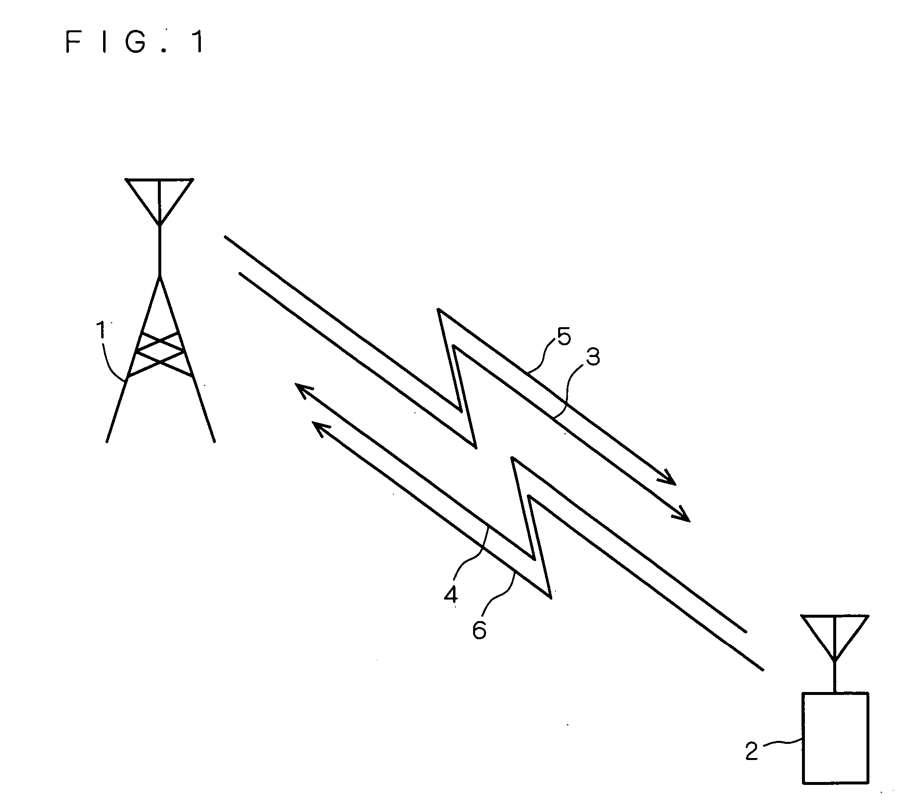
[0139]FIG. 1 is a schematic view illustrating the general structure of the communication system according to the first preferred embodiment of the present invention. The communication system includes a base station 1, a mobile station 2, and downlinks 3, 5 and uplinks 4, 6 for connecting between the base station 1 and the mobile station 2. The downlink 3 is the Release 1999-compatible downward channels (DPCCH and DPDCH). The uplink 4 is the Release 1999-com...


PUM


Abstract

The present invention relates to a mobile wireless communication system including a base station and a mobile station, and has an object to obtain a communication system capable of reducing power consumption at the mobile station without increases in processing delay and complexity of the device. To attain the above object, a base station (1) transmits control information on the number of to-be-received HS-SCCHs to a mobile station (2) through an HS-PDSCH without making the control information go through a process by an RRC layer process block (901). The mobile station (2) changes settings on the number, of to-be-received HS-SCCHs based on the control information on the number of to-be-received HS-SCCHs received from the base station (1) without making the control information go through a process by an RRC layer process block (101).

Description

TECHNICAL FIELD [0001] The present invention relates to a transmitting station (base station), a receiving station (mobile station), and a communication system (particularly a mobile wireless communication system) including the base station and the mobile station. BACKGROUND ART [0002] As a mobile wireless communication scheme, typified by a mobile phone, communication standards called the Third Generation have been adopted as IMT-2000 by the ITU (International Telecommunication Union). In Japan, commercial service of a W-CDMA (FDD) (Wideband-Code Division Multiple Access: Frequency Division Duplex) scheme has been offered since 2001. The W-CDMA (FDD) scheme aims to obtain a communication speed of approximately 2 Mbps (Mega bit per second) at each mobile station, the first specifications of which were determined as Release 1999 (or version 3.x.x) that is a standard version finalized by the standardization organization 3GPP (3rd Generation Partnership Project) in 1999. [0003] Meanwhi...

Claims


Application Information

Patent Timeline
Patent Type & Authority Applications(United States)
IPC IPC(8): H04Q7/00H04J13/00H04W52/02H04W72/12H04W76/02H04W76/04
CPCH04W72/1278H04W76/02Y02B60/50H04W76/10Y02D30/70H04W72/20
Inventor NIWANO, KAZUHITO
Owner MITSUBISHI ELECTRIC CORP
Learn More