Sputter ion pump and manufacturing method therefor and image display device with sputter ion pump

a technology of sputter ion and manufacturing method, which is applied in the direction of machines/engines, discharge tube main electrodes, and positive displacement liquid engines. it can solve the problems of reducing the exhaust efficiency, causing magnetic field leakage from the opening portion, and reducing the distance of permanent magnets correspondingly. achieve the effect of reducing the opening distance of permanent magnets, maximizing exhaust efficiency, and increasing exhaust speed

Inactive Publication Date: 2006-04-13
KK TOSHIBA
View PDF2 Cites 5 Cited by
  • Summary
  • Abstract
  • Description
  • Claims
  • Application Information

AI Technical Summary

Benefits of technology

[0013] The present invention has been made in consideration of these circumstances, and its object is to provide a small-sized sputter ion pump with high exhaust efficiency, a manufacturing method therefor, and an image display device provided with the sputter ion pump.
[0018] According to the SIP constructed in this manner, the permanent magnet can be located adjacent to the cathode by being provided in the pump container. Thus, the opening distance of the permanent magnet can be reduced to increase the exhaust speed, thereby maximizing the exhaust efficiency. Further, the permanent magnet need not be provided outside the pump container, so that the pump can be miniaturized, and the assembly workability can be improved. If at least a part of the pump container is formed of a magnetic material, moreover, the pump container can form a closed magnetic circuit to shield leaked magnetic fields.
[0019] According to the image display device provided with the SIP described above, furthermore, the interior of the vacuum envelope can be kept at a high degree of vacuum by the SIP, so that a stable display quality level can be maintained for a long time.

Problems solved by technology

However, a gap corresponding to the wall thickness of the pump container is formed between the cathode and the permanent magnet, so that the opening distance of the permanent magnet lengthens correspondingly, thereby lowering the exhaust efficiency.
If a C-shaped magnet is used as the permanent magnet, its opening portion is not magnetically shielded, so that magnetic field leakage from the opening portion is caused.
Therefore, the SIP is not suited for combination with a device that is affected by leaked magnetic fields.
Further, the permanent magnet is large, so that the pump mounting operation is poor in workability and stability, and miniaturization of the entire display device is hindered.

Method used


Image

  • Sputter ion pump and manufacturing method therefor and image display device with sputter ion pump
  • Sputter ion pump and manufacturing method therefor and image display device with sputter ion pump
  • Sputter ion pump and manufacturing method therefor and image display device with sputter ion pump

Examples


Embodiment Construction

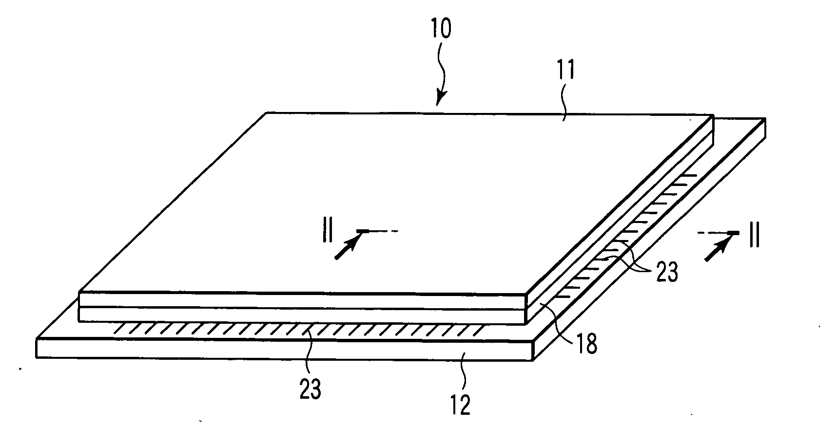
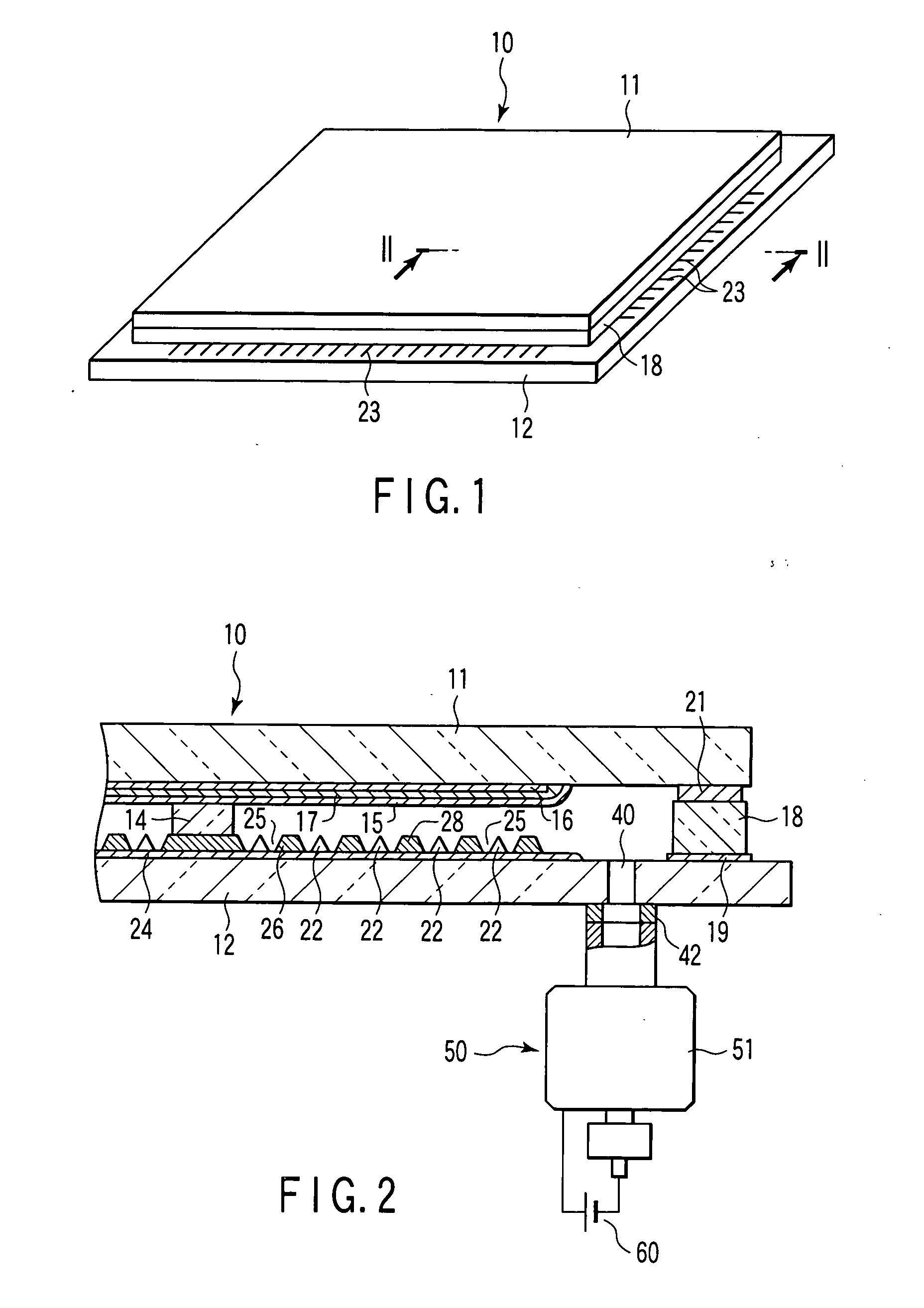
[0032] An embodiment wherein an image display device with an SIP is applied to an FED will now be described in detail with reference to the drawings.

[0033] As shown in FIGS. 1 and 2, the FED comprises a front substrate 11 and a rear substrate 12, which are formed of a rectangular glass sheet each. These substrates are opposed to each other across a gap of about 1 to 2 mm. The rear substrate 12 is formed larger than the front substrate 11. The front substrate 11 and the rear substrate 12 have their respective peripheral edge portions joined together by a sidewall 18 in the form of a rectangular frame, and constitute a flat, rectangular vacuum envelope 10 that is kept in a vacuum inside.

[0034] A plurality of plate shaped support members 14 are arranged in the vacuum envelope 10 in order to support atmospheric load that acts on the front substrate 11 and the rear substrate 12. These support members 14 individually extend parallel to one side of the vacuum envelope 10 and are arranged...


PUM


Abstract

A sputter ion pump comprises a metal pump container. In the pump container are arranged a cathode and an anode opposed to each other in the pump container and a permanent magnet situated between the cathode and the inner surface of the pump container. After locating the anode, cathode, and magnetic material in the pump container, the magnetic material is magnetized from outside the pump container, thereby forming the permanent magnet.

Description

CROSS REFERENCE TO RELATED APPLICATIONS [0001] This is a Continuation Application of PCT Application No. PCT / JP2004 / 007062, filed May 18, 2004, which was published under PCT Article 21(2) in Japanese. [0002] This application is based upon and claims the benefit of priority from prior Japanese Patent Applications No. 2003-142240, filed May 20, 2003; and No. 2003-142241, filed May 20, 2003, the entire contents of both of which are incorporated herein by reference.BACKGROUND OF THE INVENTION [0003] 1. Field of the Invention [0004] This invention relates to a sputter ion pump, a sputter ion pump manufacturing method, and an image display device with the sputter ion pump. [0005] 2. Description of the Related Art [0006] In recent years, various image display devices have been developed as a next generation of lightweight, thin display devices to replace cathode-ray tubes (hereinafter referred to as CRTs). These image display devices include a liquid crystal display (hereinafter referred t...

Claims


Application Information

Patent Timeline
Patent Type & Authority Applications(United States)
IPC IPC(8): F04B37/02H02K44/00H01J7/16H01J29/94H01J41/18
CPCH01J7/16H01J41/18H01J29/94H01J1/30H01J41/12
Inventor SEINO, KAZUYUKISHIMADA, YOSHIYUKI
Owner KK TOSHIBA
Why Eureka
Try Eureka