Vasoocclusive coil with biplex windings to improve mechanical properties

a vasoocclusive coil and coil technology, applied in the field of vasoocclusive coil improvement, can solve the problems of inherently more difficult, inability to treat or accept unacceptable risks, and inability to align the coil within the catheter, so as to improve the mechanical properties of the coil

Inactive Publication Date: 2006-04-13
DEPUY SYNTHES PROD INC
View PDF100 Cites 103 Cited by
  • Summary
  • Abstract
  • Description
  • Claims
  • Application Information

AI Technical Summary

Benefits of technology

[0011] Briefly, and in general terms, the present invention provides for a vasoocclusive device having biplex wound coils which comprises a helically wound vasoocclusive coil disposed about an inner reinforcement coil having a reverse helical winding, in which the device is deployed through a catheter to an area in the vasculature to be treated. The vasoocclusive coil with biplex windings improve the mechanical properties of the coil.
[0012] The invention accordingly provides for a vasoocclusive device for use in interventional therapy and vascular surgery that is adapted to be inserted into a portion of a vasculature. The vasoocclusive device comprises a vasoocclusive coil having a proximal and a distal end and defining a lumen between the proximal and distal ends, an inner reinforcement coil extending through the lumen of the vasoocclusive coil, and the inner reinforcement coil forms a helical winding opposite the winding of the vasoocclusive coil. Advantageously, the biplex winding improves the vasoocclusive coil mechanical properties. The dual helically wound coils of the biplex winding are configured to enhance the vasoocclusive coil stiffness without using large diameter wires in the primary. The biplex windings provide a reinforced coil structure that reduces coil interlocking and virtually eliminates kinking between coils. In a presently preferred aspect, the inner coil is wound in a helical form opposite to the winding of the outer coil to further enhance the characteristics of the biplex coil, although in another aspect the inner coil may be wound in the same direction as the outer coil.
[0013] In a presently preferred embodiment of the invention, the vasoocclusive coil biplex windings preferably extend along a longitudinal axis, the inner reinforcement coil winding being wound opposite the outer vasoocclusive coil, thereby curving about the longitudinal axis to form a hollow cylindrical pattern of helical and reversed helical coil configurations. In a preferred aspect, the biplex wound coils having proximal and distal ends are fixedly attached at the proximal ends of the vasoocclusive coil and inner reinforcement coil. The first helical coil and the second opposite wound coil may be attached by conventional methods including adhesives or heat bonding. In another presently preferred aspect, the first coil and second coil may not be fixedly attached. The second coil may be manufactured to be securely positioned within the first coil without fixation means, thereby providing a vasoocclusive coil having greater flexibility.
[0014] In another preferred embodiment, the vasoocclusive coil is formed from at least one multi-stranded micro-cable formed of a plurality of flexible strands of a resilient material. The inner reinforcement coil is also formed from at least one multi-stranded cable. By using the stranded or micro-cable construction of the invention, the vasoocclusive device becomes virtually kink resistant. In another preferred aspect, the multi-stranded biplex cable incorporates a radiopaque material in either the vasoocclusive cable, the inner reinforcement cable or preferably both coils to provide enhanced radiopacity.
[0015] The present invention also provides for a vasoocclusive device having vasoocclusive coil biplex windings and an inner reinforcement stretch resistant member extending through the vasoocclusive coil lumen to provide increased stretch resistance to the vasoocclusive coil. The reinforcement stretch resistant member also allows the coil to be pushed even when such a coil is partially deployed, to improve safety during retraction of the coil. The stretch resistant member may be formed as a ribbon, wire, braid, a coil such as a primary wind, or stranded material, and may be formed of a therapeutic or bioactive material.
[0016] In a further presently preferred embodiment, an inner strand of bioactive material may be inserted through the center of the inner coil to further enhance the mechanical characteristics of the coil assembly, improve stretch resistance and provide other benefits to the operation of the coil.

Problems solved by technology

More specifically, as smaller and more capable structures and materials have been developed, vascular defects in the human brain which were previously untreatable or represented unacceptable risks via conventional surgery have become amenable to treatment.
However, due to the tendency of such three dimensional shaped coils to transform into their expanded, final forms when introduced into a catheter in the body, they are inherently more difficult than a helical coil or a straight wire or micro-cable to push through such a catheter for delivery to a site in the vasculature to be treated, due to friction between the coil and the catheter through which it is delivered to the site to be treated, which can even result in misalignment of the coil within the catheter during delivery.
Vasoocclusive coils made of platinum, gold, and other ductile materials will easily deform from their coil shape under tension, causing a potentially dangerous situation when the coil is partially in an aneurysm and partially stretched in the delivery catheter.
If it is determined that the coil is improperly placed, or is too large, the coil will need to be moved or replaced.
However, at this stage of the procedure, the coil can no longer be pushed, and must be slowly retracted out of the catheter as a wire.

Method used


Image

  • Vasoocclusive coil with biplex windings to improve mechanical properties
  • Vasoocclusive coil with biplex windings to improve mechanical properties
  • Vasoocclusive coil with biplex windings to improve mechanical properties

Examples


Embodiment Construction

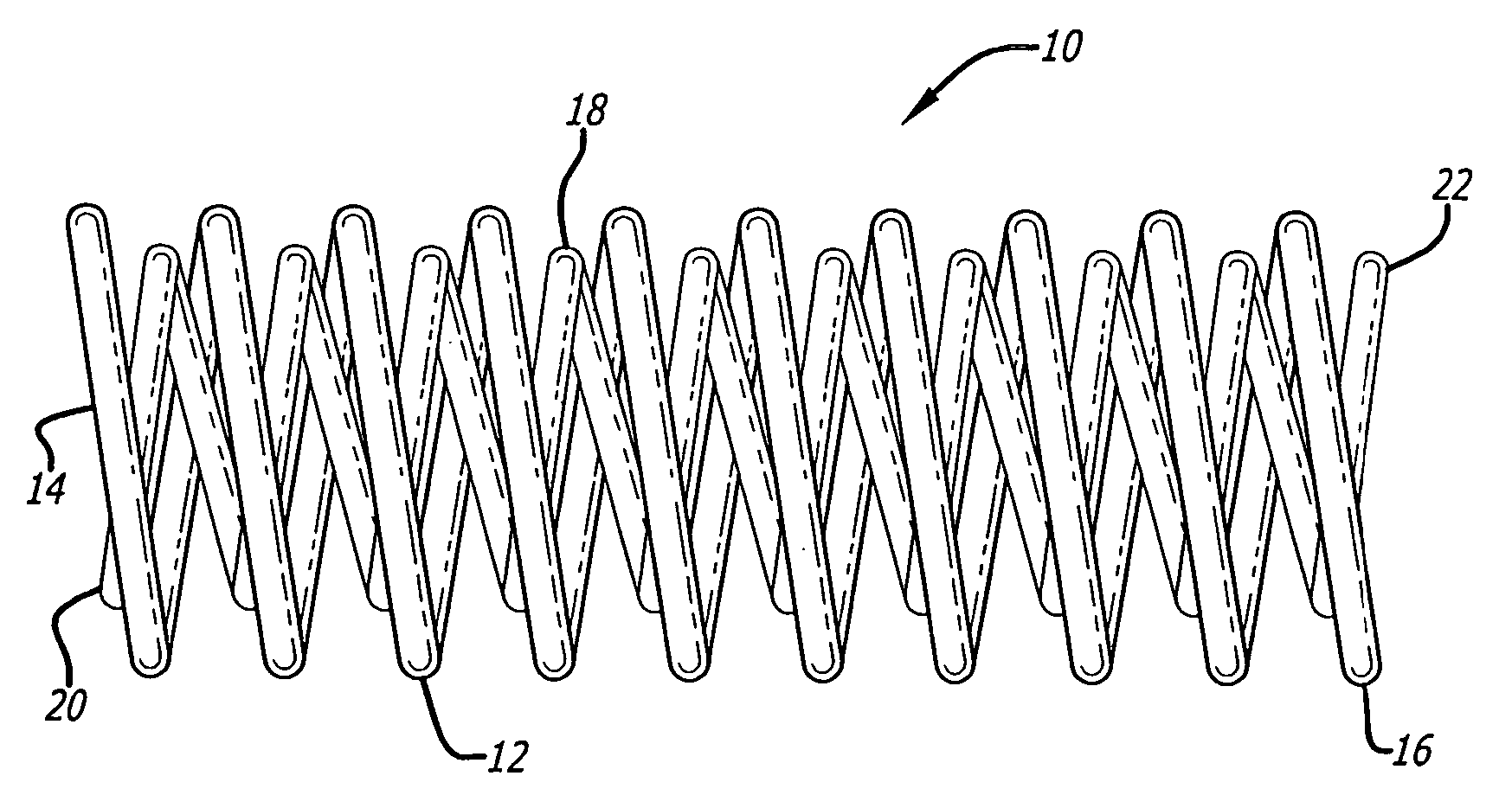
[0024] While nickel-titanium alloys are useful in forming super-elastic or shape memory interventional devices, micro-coils formed of very small diameter wires of nickel-titanium alloy material for treatment of areas of the small diameter vasculature such as an artery or vein in the brain, for treatment of aneurysms and the like, for example, can have relatively low yield strengths and are somewhat subject to kinking, even if made of super-elastic alloy. This can create problems during placement and if the coil is to be withdrawn after being emplaced by the doctor, as for instance, if the device is too small to effectively fill the cavity to be treated. Furthermore, even solid wires of a size suitable for use in interventional devices are not very radiopaque.

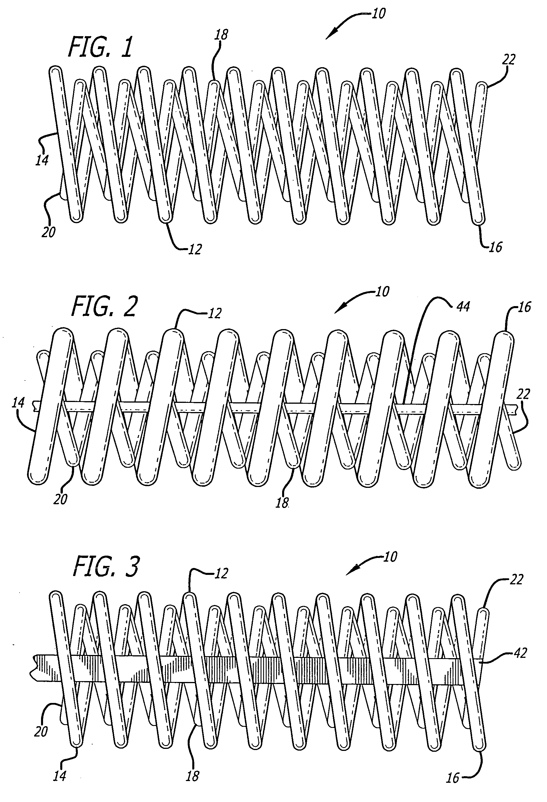
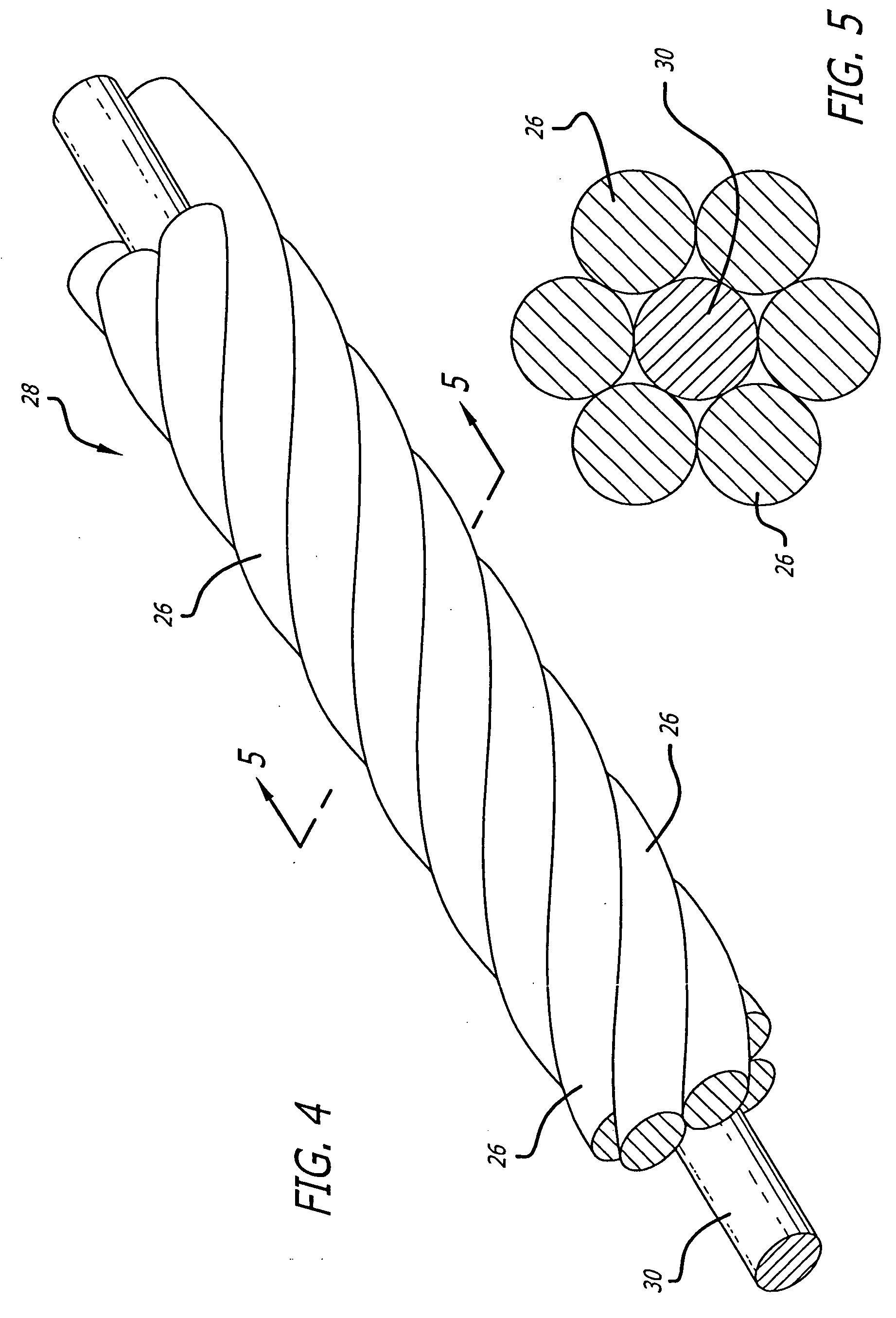
[0025] As is illustrated in the drawings, which are provided for the purposes of illustration and not by way of limitation, the invention is embodied in a micro-coil formed of at least one flexible strand of a resilient materia...


PUM


Abstract

The vasoocclusive device for use in interventional therapy and vascular surgery adapted to be inserted into a portion of a vasculature, includes a vasoocclusive coil disposed about an inner reinforcement coil wherein said vasoocclusive coil is helically wound and the inner reinforcement coil forms a reverse helical winding opposite the vasoocclusive coil winding, thereby forming a biplex wound coil. The vasoocclusive device biplex winding provides improved mechanical properties to the device. An inner reinforcement stretch resistant member attached within the biplex windings limits coil stretchability.

Description

BACKGROUND OF THE INVENTION [0001] 1. Field of the Invention [0002] This invention relates generally to devices for intravascular interventional therapeutic treatment or vascular surgery for treatment of defects in the vasculature, and more particularly concerns an improved vasoocclusive coil, such as for treatment of aneurysms. [0003] 2. Description of Related Art [0004] The art and science of interventional therapy and surgery has continually progressed towards treatment of internal defects and diseases by use of ever smaller incisions or access through the vasculature or body openings in order to reduce the trauma to tissue surrounding the treatment site. One important aspect of such treatments involves the use of catheters to place therapeutic devices at a treatment site by access through the vasculature. Examples of such procedures include transluminal angioplasty, placement of stents to reinforce the walls of a blood vessel or the like and the use of vasoocclusion devices to t...

Claims


Application Information

Patent Timeline
Patent Type & Authority Applications(United States)
IPC IPC(8): A61M29/00
CPCA61B17/12022A61B17/12113A61B17/12145A61B17/1215A61B17/12154A61B17/32056A61B2017/00477A61B2017/00526A61B2017/00862A61B2017/00867A61B2019/5466A61B17/1219A61B2090/3966
Inventor DESAI, RUPESHLEOPOLD, ERIC W.
Owner DEPUY SYNTHES PROD INC
Why Eureka
Try Eureka