Method and apparatus for the combustion of a fuel-oxidator mixture

a fuel-oxidator and mixture technology, which is applied in the direction of combustion using catalytic materials, combustion types, turbine/propulsion engine ignition, etc., can solve the adverse effects of combustion, combustion of residual oxygen, and combustion of fuel at the injection site, so as to increase the conversion rate, the influence of the main combustion is then particularly low, and the pilot flame stability increases.

Inactive Publication Date: 2006-04-20
ANSALDO ENERGIA SWITZERLAND AG
View PDF11 Cites 43 Cited by
  • Summary
  • Abstract
  • Description
  • Claims
  • Application Information

AI Technical Summary

Benefits of technology

[0007] The invention is based on the general concept of only partially oxidizing a rich pilot fuel-oxidator mixture in a catalyst, in such a manner that highly reactive hydrogen is formed, with the partially oxidized, hydrogen-containing mixture together with an additional oxidator flow being introduced into at least one zone which is suitable for stabilizing the combustion of the main fuel-oxidator mixture. With this procedure, the oxidator required for the full oxidation of the partially oxidized pilot mixture is also introduced or injected into the zones which are suitable for stabilizing combustion, thereby increasing the stability of the pilot flames generated in this way. At the same time, the pilot flames, during combustion, extract no oxidator or at least significantly less oxidator from the main mixture, with the result that the main mixture reaction can also take place in a more stable way.
[0008] It has proven particularly expedient for stabilization of the combustion of the main mixture for the hydrogen-containing, partially oxidized pilot mixture and the additional oxidator flow to be dimensioned so as to form a lean mixture. In particular, it may be desirable to achieve a slightly lean mixture which has only a relatively low excess of oxidator. The influence on the emissions of the main combustion is then particularly low.
[0009] According to a particularly advantageous embodiment, the oxidator flow which is additionally supplied and is also referred to below as a heat-exchanging oxidator flow can be used to preheat the pilot fuel-oxidator mixture and / or to cool the catalyst. The oxidator used in a turbogroup generally originates from the delivery side of a compressor, so that the oxidator, usually air, is already at a relatively high temperature. The injection of the fuel into a part-flow of the oxidator originating from the compressor forms a pilot fuel-oxidator mixture, the temperature of which is below the temperature of the compressed oxidator, since the fuel, usually natural gas, is at a relatively low temperature when it is injected. Accordingly, another part-flow of the oxidator originating from the compressor can be used to preheat the pilot fuel-oxidator mixture by effecting suitable thermal coupling. As a result, the ignition limit of the catalytic reaction is reached after only a relatively short inlet distance into the catalyst, with the result that at the same time an increased conversion rate can be achieved in the catalyst. The catalytic reaction then increases the temperature of the catalyst. To ensure that predominantly the desired partial oxidation takes place in the catalyst, the temperature in the catalyst must not rise excessively, since otherwise full oxidation can take place and / or a homogeneous gas reaction may occur. The heat-exchanging oxidator flow is especially suitable for cooling the catalyst, in particular after it has released heat to the pilot fuel-oxidator mixture. This allows the desired partial oxidation reaction in the catalyst to be stabilized.
[0010] According to a preferred embodiment, the catalyst may have a plurality of channels through which medium can flow in parallel and of which some are catalytically active and the others are catalytically inactive. The catalytically active channels in this case form a catalytically active path through the catalyst which is configured in such a way that, as the rich pilot fuel-oxidator mixture flows through it, it allows the desired partial oxidation with hydrogen being formed. The catalytically inactive channels form a catalytically inactive path through the catalyst, and the heat-exchanging oxidator flow flows through this catalytically inactive path in operation. The channels are coupled to one another in such a manner as to exchange heat on account of the channels being of uniform design, i.e. the channels being accommodated in a common structure of the catalyst. This design therefore on the one hand allows the pilot fuel-oxidator mixture which has been introduced into the catalyst to be preheated and on the other hand allows the catalyst to be cooled. Suitable matching of the catalytically active channels and the catalytically inactive channels, in particular in terms of their number, arrangement and dimensions, makes it possible to achieve a targeted heat management for the catalyst which is designed for an rated operating state of the apparatus, in particular of the turbogroup. This allows the catalyst to have a long service life and also allows reproducible combustion reactions to be established in the catalyst and therefore in the stabilization zones.

Problems solved by technology

Injecting the synthesis gas, which is highly reactive on account of the hydrogen fractions, causes flames to form at the injection locations, consuming residual oxygen from the lean main combustion.
Consequently, these burners are very susceptible to combustion instabilities and are moreover exposed to extensive pressure fluctuations, which has an adverse effect on the service lives of the burner, of a downstream combustor and of a gas turbine and its blades and vanes.

Method used


Image

  • Method and apparatus for the combustion of a fuel-oxidator mixture
  • Method and apparatus for the combustion of a fuel-oxidator mixture
  • Method and apparatus for the combustion of a fuel-oxidator mixture

Examples


Embodiment Construction

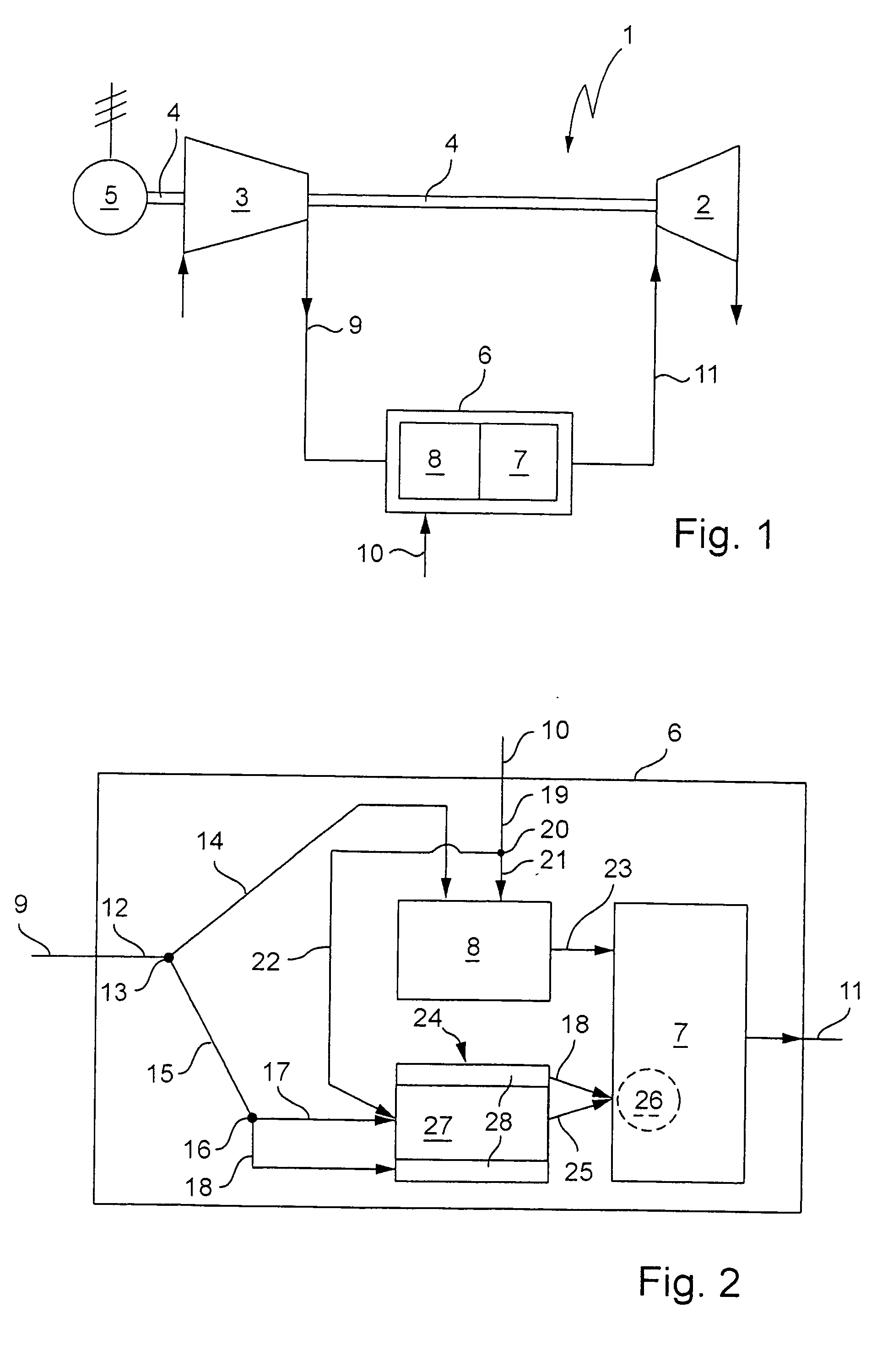
[0020] In accordance with FIG. 1, a turbogroup 1 comprises a turbine 2, which is designed in particular as a gas turbine, and a compressor 3, which is connected to the turbine 2 via a drive shaft 4. It is customary for the turbogroup 1 to be used in a power plant, in which case the turbine 2 additionally drives a generator 5 via the shaft 4.

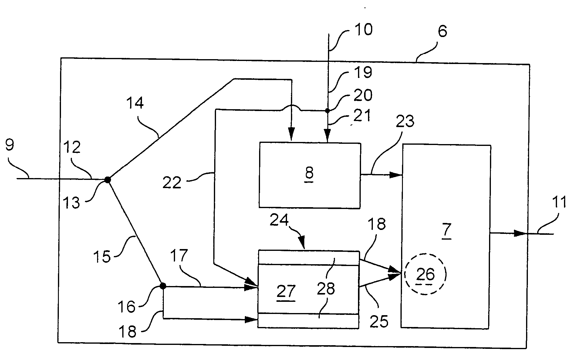
[0021] Moreover, the turbogroup 1 comprises a combustion system, referred to as combustor 6, which has at least one combustion chamber 7 and at least one premix burner 8 connected upstream of this combustion chamber 7. On the entrance side, the combustor 6 is connected to the high-pressure side of the compressor 3, and on the exit side it is connected to the high-pressure side of the turbine 2. Accordingly, the combustor 6 is supplied with oxidator, in particular air, via an oxidator pipe 9 from the compressor 3.

[0022] The fuel supply is effected via a corresponding fuel pipe 10. The hot combustion gases are fed to the turbine 2 via a hot gas p...


PUM


Abstract

The present invention relates to a method and an apparatus (6) for carrying out the method, the method being used for combustion of a fuel-oxidator mixture in a combustion chamber (7) of a turbogroup, in particular of a power plant. A total oxidator flow (12) is divided into a main oxidator flow (14) and a secondary oxidator flow (15). The main oxidator flow (14) is lean mixed with a main fuel flow (21) in a premix burner (8), and the mixture (23) is fully oxidized in the combustion chamber (7). The secondary oxidator flow (15) is divided into a pilot oxidator flow (17) and a heat-exchanging oxidator flow (18). The pilot oxidator flow (17) is rich mixed with a pilot fuel flow (22), and the mixture (17, 22) is partially oxidized in a catalyst (24), with hydrogen being formed. Downstream of the catalyst (24), the partially oxidized pilot fuel-oxidator mixture (25) and the heat-exchanging oxidator flow (18) are together introduced into at least one zone (26) which is suitable for stabilizing the combustion of the main fuel-oxidator mixture (23).

Description

FIELD OF THE INVENTION [0001] The present invention relates to a method and apparatus for the combustion of a fuel-oxidator mixture in a combustion chamber of a turbogroup, in particular of a power plant. DISCUSSION OF BACKGROUND [0002] EP 0 849 451 A2 has disclosed a method for operating a gas turbogroup, the gas turbogroup substantially comprising a compressor, a combustor, a turbine and a generator. Air that has been compressed in the compressor and fuel are mixed in a premixer of the combustor prior to combustion and are then burnt in a combustion chamber. Compressed air supplied via a partial air pipe is mixed with fuel supplied via a partial fuel pipe, and the mixture is introduced into a reactor having a catalytic coating. In the reactor, the fuel mixture is converted into a synthesis gas, comprising hydrogen, carbon monoxide, residual air and residual fuel. This synthesis gas is injected into zones of the combustor in which it stabilizes the flame. Injecting the synthesis ga...

Claims


Application Information

Patent Timeline
Patent Type & Authority Applications(United States)
IPC IPC(8): F23R3/40F23C13/00
CPCF23C13/00F23C2900/13002F23C2900/9901F23R3/40
Inventor GRIFFIN, TIMOTHYWINKLER, DIETER
Owner ANSALDO ENERGIA SWITZERLAND AG
Why Eureka
Try Eureka