
Method for operating and/or reviewing a magneto-inductive flow meter

a technology of inductive flow meter and flow rate, which is applied in the direction of fluid speed measurement, level indicator, testing/calibration of speed/acceleration/shock measurement device, etc., can solve the problem of not being able to obtain further reliable measurement results, the stated accuracy of measured values cannot be guaranteed, and the measuring operation of the measuring device can be ended. , to achieve the effect of reducing the rise time of the magnetic field, reducing the eddy current, and simple manner

Active Publication Date: 2006-04-20
ENDRESS HAUSER FLOWTEC AG
View PDF4 Cites 29 Cited by
  • Summary
  • Abstract
  • Description
  • Claims
  • Application Information

AI Technical Summary

Benefits of technology

[0017] It is, therefore, an object of the invention to provide a method, by means of which eddy currents can be decreased in the magnetic field system and by means of which, to such extent, a lessening of the rise time of the magnetic field, as it undergoes its rhythmic pole reversal and accompanying, repetitive, build-up anew. Additionally, an object of the invention is to provide a method with which a flow meter of the described kind can be reviewed as it is running and, to such extent, malfunctions of the measuring device can be registered very accurately and in simple manner, and, as required, can also be located.
[0029] A basic idea of the invention is to lessen the rise time of the repetitively newly established magnetic field by applying a counter-voltage for a short time after the reaching of the maximum electrical current value for the exciter current and, thus, to lengthen, for example, the time span with constant exciter current, at, in comparison to conventional magneto-inductive flow meters, a half-period which remains essentially constant in length.

Problems solved by technology

For example, measuring operation of the measuring device can be ended, since, in such case, no further reliable measurement results can be obtained.
Especially, the case can arise, namely, that individual components of the measuring device only slightly deviate from their desired values, so that each individual component is noted within the framework of a self-test as fully capable of functioning, yet, in the interaction of the components, a measuring operation is generated, which is faulty, such that the stated accuracy of the measured values cannot be assured.
This disadvantageous effect of the eddy currents occurs also in the case of, and despite, the mentioned increased voltage.

Method used


Image

  • Method for operating and/or reviewing a magneto-inductive flow meter
  • Method for operating and/or reviewing a magneto-inductive flow meter
  • Method for operating and/or reviewing a magneto-inductive flow meter

Examples


Embodiment Construction

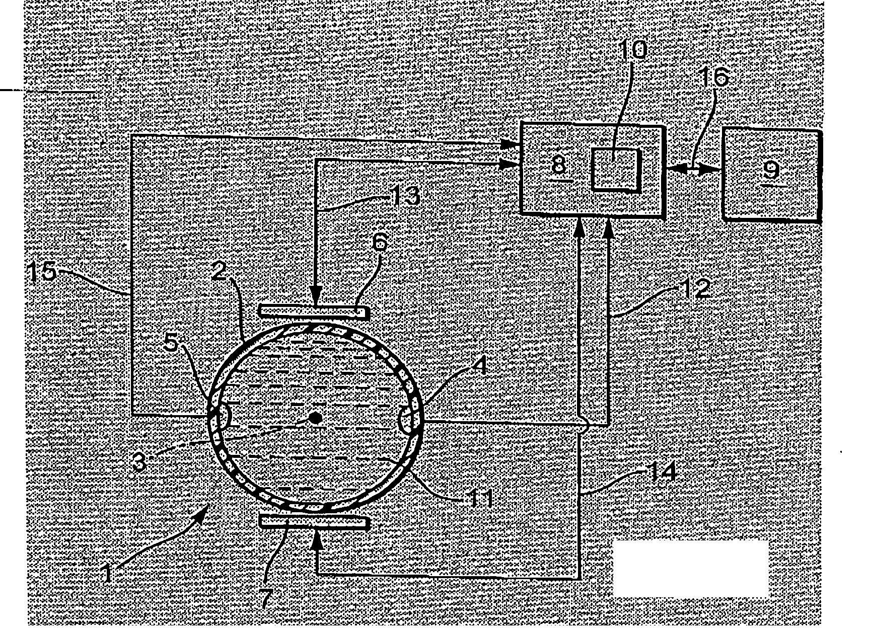
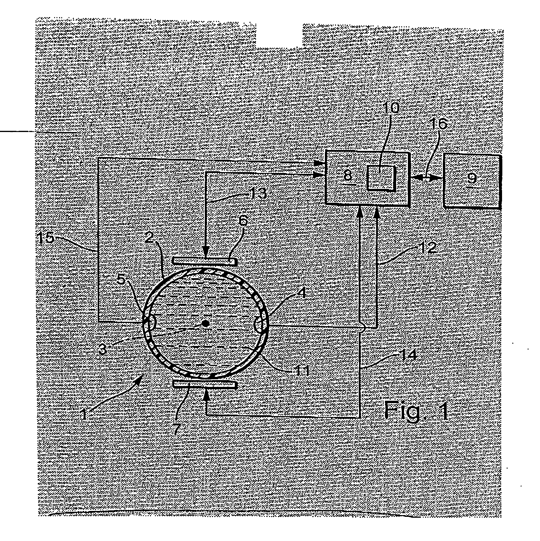
[0044]FIG. 1 shows schematically and partially in the form of a block diagram a magneto-inductive flow meter suitable for carrying-out the method of the invention. By means of this flow meter, measured values can be produced for at least one physical variable of a medium, especially a fluid, flowing in a pipeline (not shown). For example, the flow meter can be used for measuring a volume flow rate and / or a flow velocity of an electrically conducting liquid.

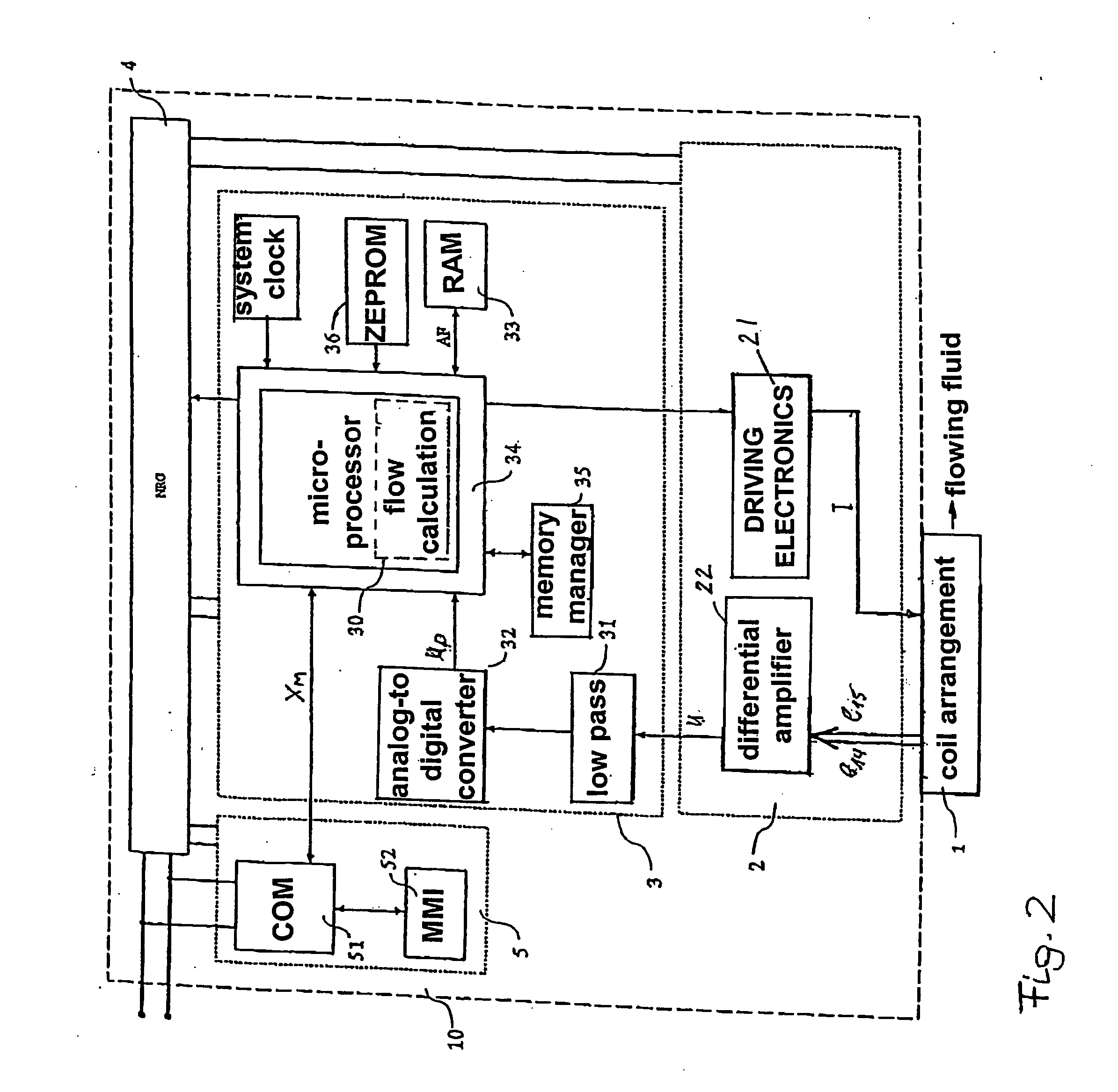
[0045] The flow meter shown here includes a flow pickup 1 for producing measured potentials corresponding to the physical variable to be measured, a measuring device electronics having a microcomputer, especially a measuring and operating circuit 2, especially one implemented, at least in part, by means of the microcomputer, for registering the measuring potentials and for producing at least one measurement signal corresponding with the physical variable, as well as an evaluating circuit 3, especially one realized by means of the...


PUM


Abstract

A flow meter includes a measuring tube for conveying a fluid to be measured and a magnetic field system, which has at least one field coil, through which an exciter current (IM) flows, at least at times, for producing a magnetic field passing through the fluid at least partly perpendicularly to a stream direction. In the method, the voltage (UH) instantaneously driving the exciter current (IM) is changed at a second point in time, t2, from the second voltage level, Udrv, to a third voltage level, Ushort, especially to a third voltage level which is constant or controlled to be constant, in order to achieve a sinking of the electrical current strength of the exciter current (IM) instantaneously flowing in the at least one field coil from the maximum current value, Im, to an electrical current end value, Iczu, especially a constant end value, predetermined for the exciter current (IM) In such case, the third voltage level, Ushort, is chosen smaller than the second voltage level, Urev. For determining a third point in time, t3, which corresponds to the reaching of the electrical current end value, Ic, the exciter current IM is registered, at least at times. Based on this, a first time constant, Tshort, for the magnetic field system is determined, which corresponds to a time span, t3−t2, lying between the second point in time, t2, and the third point in time, t3, and / or a second time constant, Trev+Tshort, for the magnetic field system, which corresponds to a time span, t3−t1, lying between the first point in time, t1, and the third point in time, t3. For determining a diagnosis value representing an instantaneous operating state of the flow meter, the determined first time constant, Tshort, is then compared with a predetermined first reference value, T1ref, and / or the determined second time constant, Trev+Tshort, is compared with a predetermined second reference value, T2ref.

Description

FIELD OF THE INVENTION [0001] The invention relates to a method for reviewing a magneto-inductive flow meter having a measuring tube for conveying a fluid to be measured, a magnetic field system, which has at least one field coil flowed through, at least at times, by an exciter current for producing a magnetic field passing through the fluid at least, in part, perpendicularly to a stream, or flow, direction. BACKGROUND OF THE INVENTION [0002] For measuring electrically conductive fluids, flow meters using a magneto-inductive flow pickup are often employed. In the following, when necessary, for the sake of simplicity, discussion will only be in terms of flow pickups, or flow meters, as the case may be. As is known, magneto-inductive flow meters permit measurement of the volume flow rate of an electrically conductive liquid flowing in a pipeline and the reflecting of such in a corresponding, measured value; thus, the volume of liquid flowing through a pipe cross section per unit time ...

Claims


Application Information

Patent Timeline
IPC IPC(8): G01F1/56
CPCG01F1/60G01F25/0007G01F25/10
Inventor BUDMIGER, THOMAS
Owner ENDRESS HAUSER FLOWTEC AG
Learn More