Label applicator system

a technology of applicator and label printer, which is applied in the direction of controlling lamination, mechanical actuation of burglar alarms, instruments, etc., can solve the problems of additional time, obviating the need for additional verification devices, and reducing so as to improve the accuracy of rfid programming results

Active Publication Date: 2006-04-20
ILLINOIS TOOL WORKS INC
View PDF12 Cites 19 Cited by
  • Summary
  • Abstract
  • Description
  • Claims
  • Application Information

AI Technical Summary

Benefits of technology

[0020] The present invention pertains to an improved print label applicator assembly, and in particular, to one that can print, program, apply and verify proper programming of RFID labels. The applicator assembly includes an RF assembly, which includes an RF antenna, an RFID engine and an antenna cable, coupled to a tamp assembly. In other embodiments, the applicator machine also includes a print engine. In one embodiment, the tamp assembly includes a tamp pad comprised of a non-metallic material, and the RF antenna is coupled to the tamp pad—thus obviating the signal degradation problems caused by metallic printer heads that legacy machines are encumbered by. Further, the tamp pad application process is a relatively slow one, providing the RF antenna additional time to program the RFID label; Enhanced RFID programming accuracy results.

Problems solved by technology

Further, the tamp pad application process is a relatively slow one, providing the RF antenna additional time to program the RFID label; Enhanced RFID programming accuracy results.
As a result, the same RF assembly coupled to the tamp assembly serves as the verification device, obviating the need for additional, costly and error prone verification devices that are positioned down stream in legacy assemblies.

Method used


Image

  • Label applicator system
  • Label applicator system
  • Label applicator system

Examples


Embodiment Construction

[0033] While the present invention is susceptible of embodiment in various forms, there is shown in the drawings and will hereinafter be described a presently preferred embodiment with the understanding that the present disclosure is to be considered an exemplification of the invention and is not intended to limit the invention to the specific embodiment illustrated.

[0034] It should be further understood that the title of this section of this specification, namely, “Detailed Description Of The Invention”, relates to a requirement of the United States Patent Office, and does not imply, nor should be inferred to limit the subject matter disclosed herein.

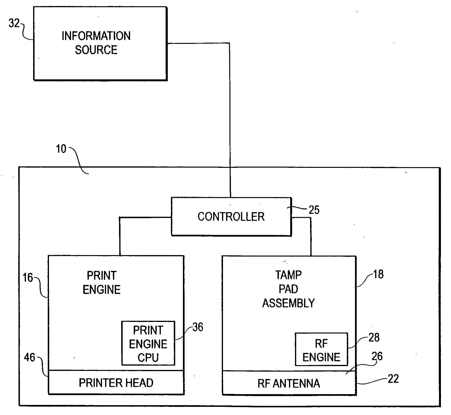
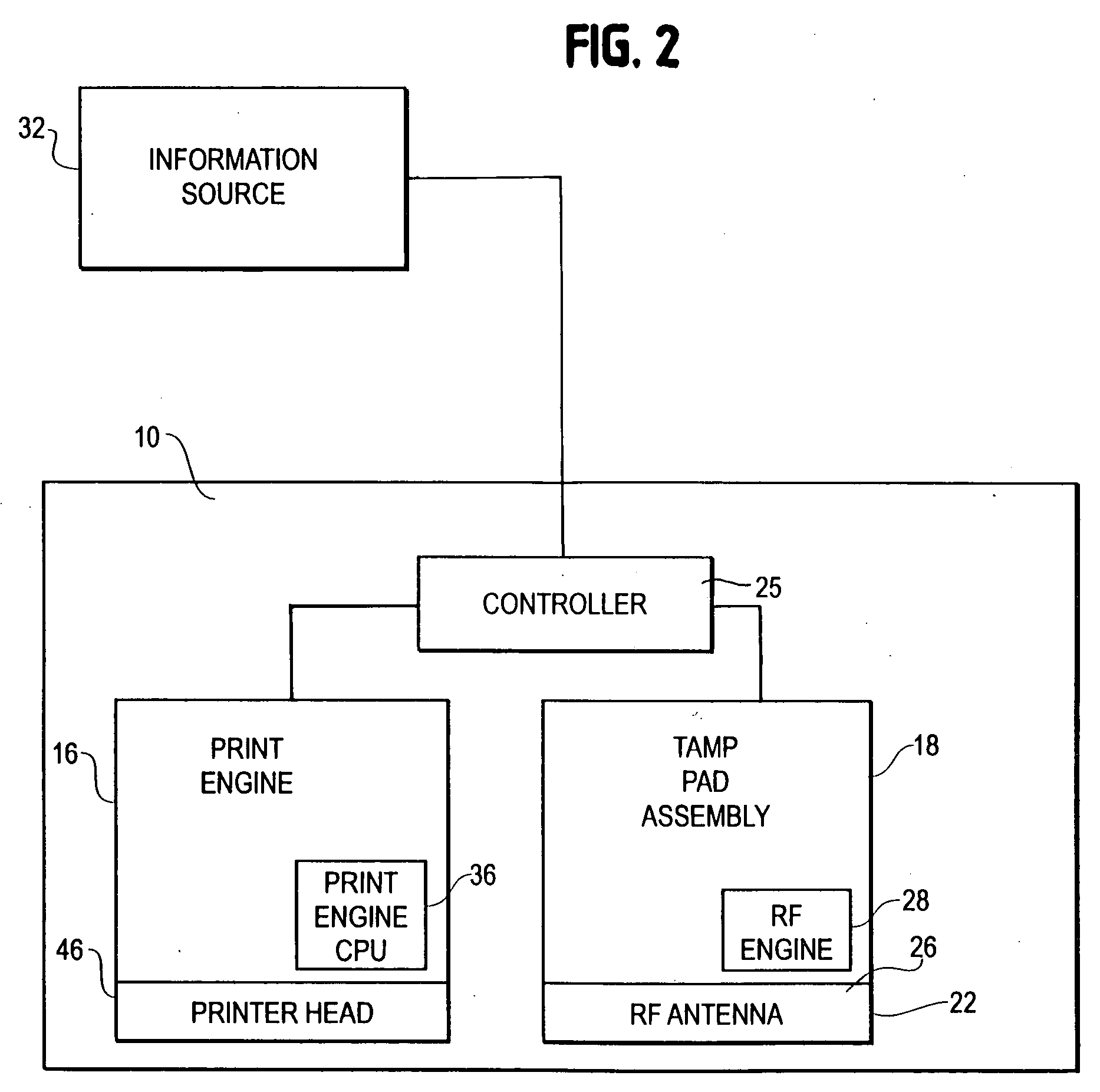
[0035] The present invention pertains to an improved print label applicator assembly, and in particular, to one that can print, program, and verify proper programming of RFID labels. The applicator assembly includes an RF assembly, which includes an RF antenna, a RFID engine and antenna cable, coupled to a tamp assembly. In some embo...


PUM

PropertyMeasurementUnit
flexibleaaaaaaaaaa
frictionaaaaaaaaaa
vacuumaaaaaaaaaa

Abstract

A label printer applicator system programs labels having integrated circuits therein and applies the labels to a package. The applicator includes a tamp assembly having a tamp pad movement assembly and a tamp pad coupled thereto. An RF assembly, including an RF antenna, an RFID engine and antenna cable, is coupled to the tamp assembly. The tamp pad moves from a receiving position, where it receives a non-programmed label, to an extended position, where it applies the label to a package. The RFID engine provides RFID information to the RF antenna, which sends RFID information signals to the label to program the label. After the RFID label is applied to the package, the RF assembly sends test signals to the RFID label to determine whether the label has been properly programmed.

Description

BACKGROUND OF THE INVENTION [0001] The present invention relates to a label printer applicator system. More particularly, the present invention pertains to a label printer applicator system that is capable of applying Radio Frequency Identification (RFID) labels to objects. [0002] Automated label printer applicators or label machines are well known in the art. Such a machine prints labels on a continuous web of label material (which web material includes a carrier or liner and a series of discrete labels adhered to the liner at intervals along the liner), feeds the web, removes the labels from the liner and applies the labels to the objects. Although the applicators may be used in a variety of contexts, they are commonly used to apply labels to packages or products that are shipped from a manufacturer, wholesale entity or distributor to a retailer or other customer. [0003] Known label machines include, generally, a supply roll on which the web is wound. The web is fed from the suppl...

Claims


Application Information

Patent Timeline
Patent Type & Authority Applications(United States)
IPC IPC(8): H04Q5/22G06F17/00G01R31/28
CPCB65C9/1884B65C9/40Y10T29/49004G06K17/0025B65C2009/407
Inventor DODS, STEVEN M.
Owner ILLINOIS TOOL WORKS INC
Why Eureka
Try Eureka