DC offset calibration system

Inactive Publication Date: 2006-04-20
PANASONIC CORP
View PDF4 Cites 17 Cited by
  • Summary
  • Abstract
  • Description
  • Claims
  • Application Information

AI Technical Summary

Benefits of technology

[0032] As described above, the DC offset calibration system according to the present invention permits neglecting the influence of an output signal or spurious of one of the frequenc

Problems solved by technology

Under the direct conversion system, however, if a secondary nonlinear distortion is present in the mixer circuit, a DC offset emerges in an output base band signal when the level of the input signal is high.
Accordingly, the direct conversion system has a drawback that the receiving sensitivity is degraded because of the presence of the DC offset 603 in the frequency band of the desired signal 601 in the mixer output.
However, the perfect symmetry of the elements constituting the differential circuit cannot be practically achieved because of manufacturing variation among individual units, and hence it is impossible to eliminate

Method used


Image

  • DC offset calibration system
  • DC offset calibration system
  • DC offset calibration system

Examples


first embodiment

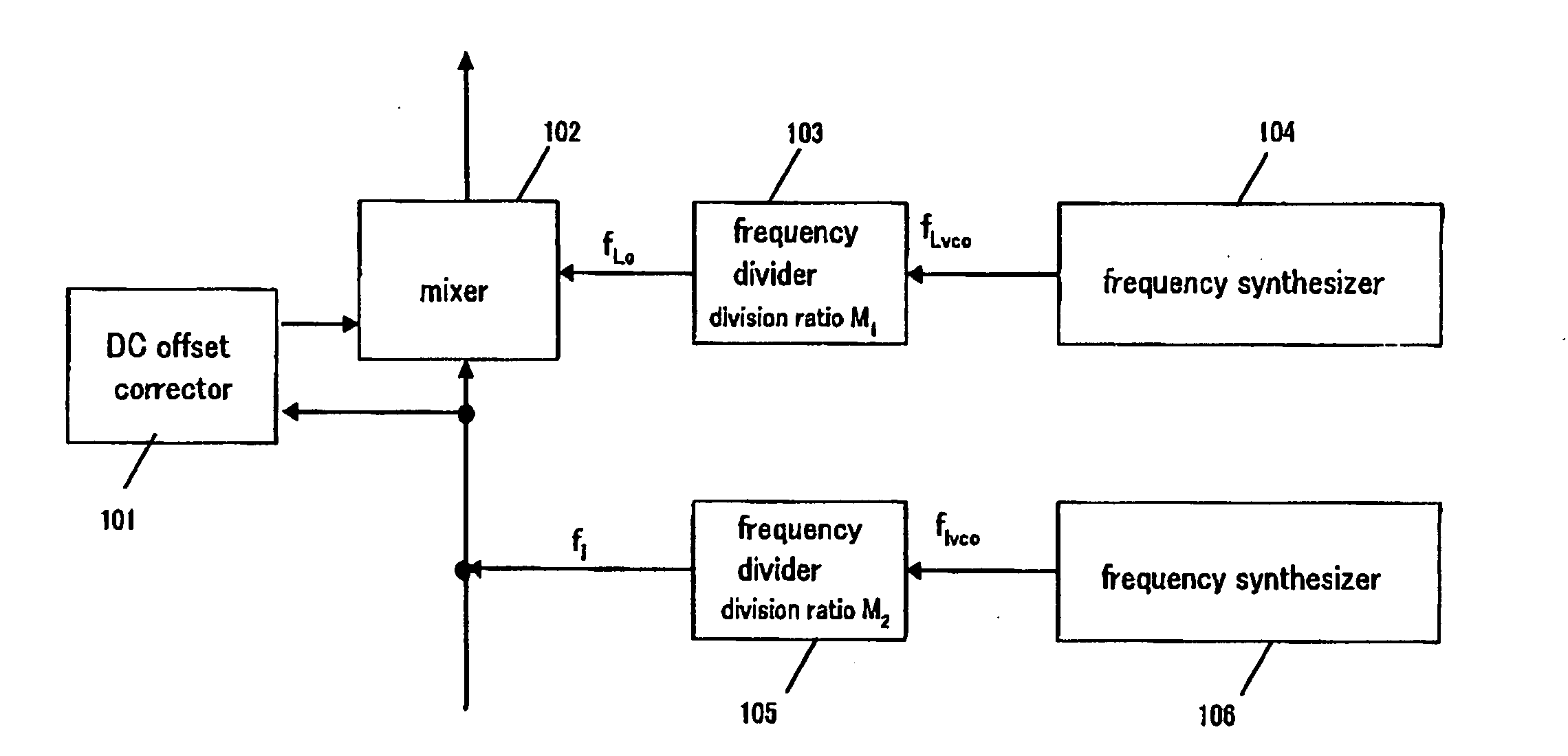
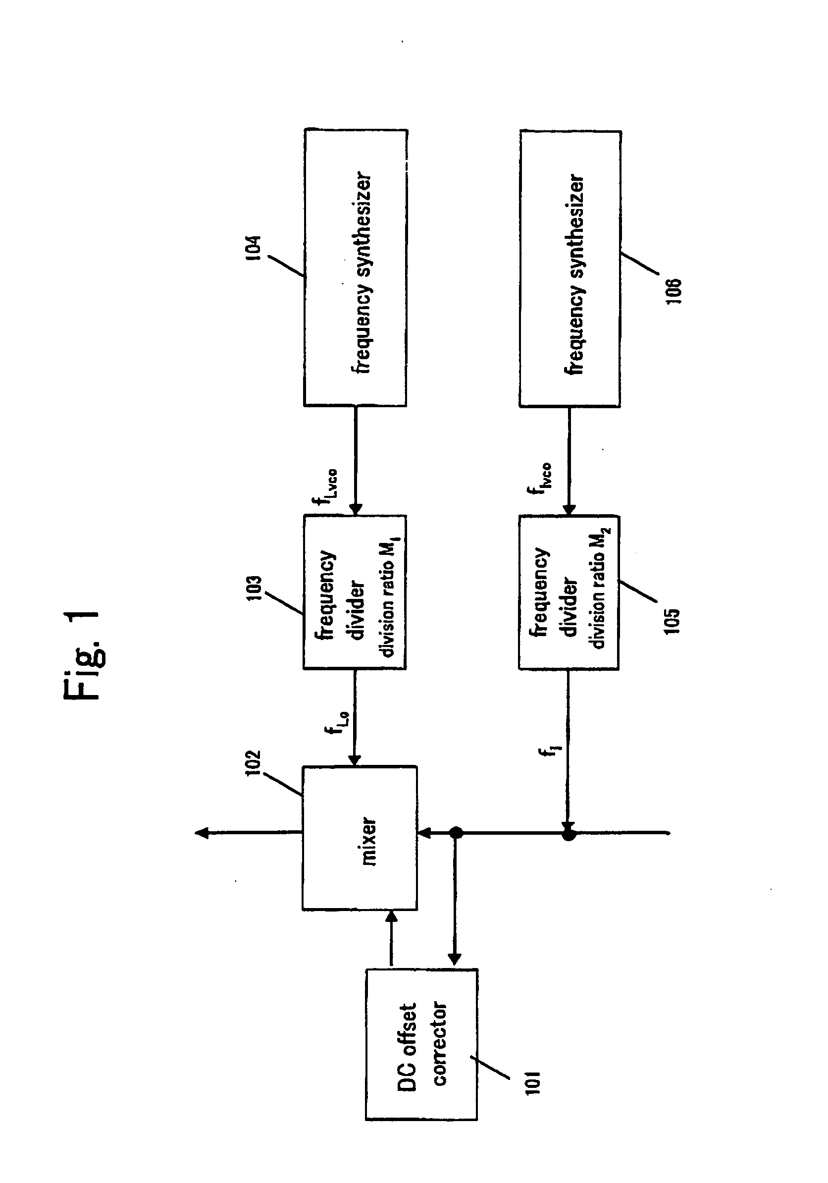
[0040] Referring first to FIG. 1, the present invention will be described. A frequency divider 103 divides the frequency of a frequency signal fLvco of a frequency synthesizer 104 at a division ratio M1, to thereby output a frequency signal fLo and input the frequency signal fLo to a mixer 102 as a local signal.

[0041] Likewise, a frequency divider 105 divides the frequency of a frequency signal fIvco of a frequency synthesizer 106 at a division ratio M2, to thereby output a frequency signal fI and input the frequency signal fI to the mixer 102 and a DC offset corrector 101 as a RF interfering signal. The DC offset corrector 101 has a similar configuration to FIG. 6.

[0042] Here, the relation among the local signal fLo, the frequency signal fLvco and the division ratio M1, as well as among the interfering signal fI, the frequency signal fIvco and the division ratio M2 can be defined as the following formulas (1) and (2).

fLo=fLvco / M1   (1)

fI=fIvco / M2   (2)

[0043] It is to be assumed...

second embodiment

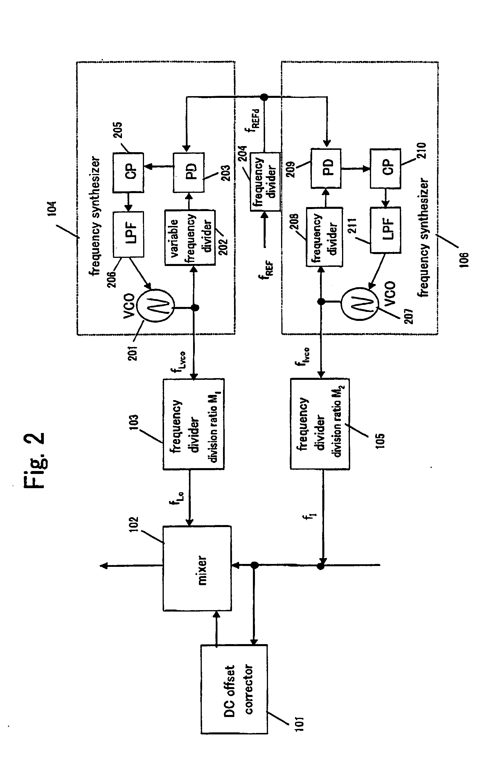
[0051] Now referring to FIG. 2, the present invention will be described. The frequency synthesizer 104 that generates the local signal fLO includes a voltage control oscillator (VCO) 201, a variable frequency divider 202 that divides the frequency of that signal, a phase comparator (PD) 203 that compares an output signal of the variable frequency divider 202 and a phase comparison reference signal fREFd so as to output a signal proportionate to the phase difference, a charge pump (CP) 205 that converts the signal from the phase comparator 205 into a current, and a low pass filter (LPF) 206 that smoothens the output signal of the charge pump 205 and outputs the smoothened signal to a control terminal of the voltage control oscillator 201 as a control signal.

[0052] Likewise, the frequency synthesizer 106 that generates the interfering signal fI includes a voltage control oscillator 207, a frequency divider 208 that divides the frequency of that signal, a phase comparator 209 that comp...

third embodiment

[0057]FIG. 3 shows a configuration of a compatible with a dual band device, according to the present invention; This DC offset calibration system includes two mixers 102, 302 to handle two different bands namely a band 1 and a band 2, and the respective mixers 102, 302 include a DC offset corrector 101, 301. The DC offset correctors 101, 301 have a similar configuration to FIG. 6. The mixers 102, 302 receive a local signal fLo, fLo2, and an interfering signal fI, fI2 respectively. The mixer 102 corresponds to the band 1, and the mixer 302 corresponds to the band 1.

[0058] A feature of the third aspect of the present invention is that a frequency synthesizer 306 that generates fI and fI2 as an interfering signal does not have a frequency switching function. In other words, the frequency synthesizer 306 is the same as the frequency synthesizer 106 in FIG. 2, but with a fixed frequency divider 305 instead of the frequency divider 208. Also, frequency dividers 303, 304 are employed in pl...


PUM


Abstract

A division ratio of a first frequency divider that generates a local signal and a division ratio of a second frequency divider that generates a RF interfering signal are different, and a first frequency synthesizer that generates the local signal and a second frequency synthesizer that generates the RF interfering signal employ an identical reference signal. The second frequency synthesizer that generates the RF interfering signal is not provided with a frequency switching function.

Description

BACKGROUND OF THE INVENTION [0001] 1. Field of the Invention [0002] The present invention relates to a DC offset calibration system that corrects a DC offset which emerges when an interfering signal is input in a direct conversion type radio receiver. [0003] 2. Description of the Related Art [0004] Existing mobile phones include a dual band mobile phone compatible with signals of two different frequency bands, for example bandwidths of 880 to 915 MHz allocated to GSM (Global System for Mobile Communication) and 1710 to 1785 MHz allocated to DCS (Digital Cellular System). Some of such dual band mobile phones include a frequency synthesizer so as to handle two frequency bands by switching the frequency of a local signal. [0005] Lately, however, there is a growing demand for a triple band mobile phone that is compatible with signals of 1850 to 1915 MHz allocated to PCS (Personal Communication System), in addition to the GSM and DCS. Thus, compatibility with still more frequency bands w...

Claims


Application Information

Patent Timeline
IPC IPC(8): H04B1/00H04B1/10H04L25/06
CPCH04B1/005H04B1/406H04B15/06H04L25/061
Inventor IRIE, MASATAKEKOMORI, HIROSHI
Owner PANASONIC CORP
Why Eureka
Try Eureka