Filled epoxy resin compositions

Inactive Publication Date: 2006-04-20
YAZAKI CORP
View PDF9 Cites 34 Cited by
  • Summary
  • Abstract
  • Description
  • Claims
  • Application Information

AI Technical Summary

Benefits of technology

[0023] The invention also resides in a method for making an encapsulant of the kind described above. The method includes steps of (1) processing a glass characterized by a glass refractive index in the range of 1.48 to 1.60, with a variance of less than about 0.001, to form filler particles having diameters between 1 μm and 500 μm and characterized by a filler refractive index, (2) preparing an epoxy resin composition characterized by the refractive index of an epoxy resin composition at a cured stage, wherein the filler refractive index and the refractive index of the epoxy resin composition at a cured stage are sufficiently similar such that the encapsulant has optical transmittance of at least 20% when measured at a wavelength in the range of 400 nm to 900 nm at an encapsulant thickness of about 1 mm, (3) mixing the epoxy resin composition with the filler particles to form a filled epoxy resin composition, (4) encapsulating the optoelectronic device with the filled epoxy resin composition, and (5) curing the filled epoxy resin composition encapsulating the optoelectronic device.
[0024] In more detailed features of the method of the invention, the step of processing a glass includes processing the glass to form filler particles having diameters between 1 μm and 250 μm. The volume percentage of such filler particles having diameters less than 10 μm preferably is less than 60 percent, more preferably is less than 20%, and most preferably is less than 10%. Most preferably, all of the glass filler particles have diameters between 10 μm and 250 μm.
[0025] In other, more detailed features of the invention, the method further includes a step of heating the filler particles in an oxygen-containing atmosphere after the step of processing a glass to form filler particles. Such heating occurs at a preferred temperature less than or equal to the strain point of the glass, and more preferred temperature between 20° C. and the strain point of the glass. Such heating has a duration preferably of at least about 1 hour, more preferably between 5 and 50 hours, and most preferably between 30 hours and 40 hours. The heating preferably occurs in dry air. In another more detai

Problems solved by technology

This sintering is achieved at a very high temperature range of 1,050° C. to 1,250° C. The disclosed filler manufacturing method has the disadvantages of being complicated and expensive, as well as requiring lengthy preparation time and high sintering temperature.
Additional disadvantages include possible phase separation, crystallization, and coloring of TiO2 at the high sintering temperatures required using the method.
Phase separation and crystallization cause intolerably high refractive index differences between the

Method used


Image

  • Filled epoxy resin compositions
  • Filled epoxy resin compositions
  • Filled epoxy resin compositions

Examples


example 1

Encapsulant Prepared from a Binary Epoxy Mixture

[0092] An encapsulant prepared from a binary epoxy mixture within the scope of the present invention is prepared in this illustrative Example.

Preparation of the Filler Particles:

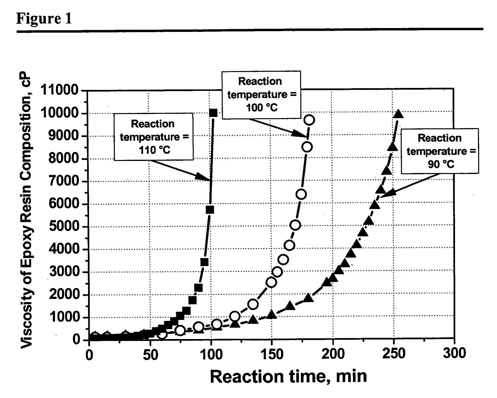
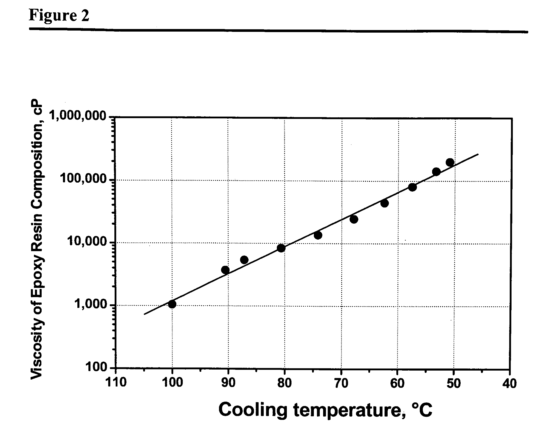
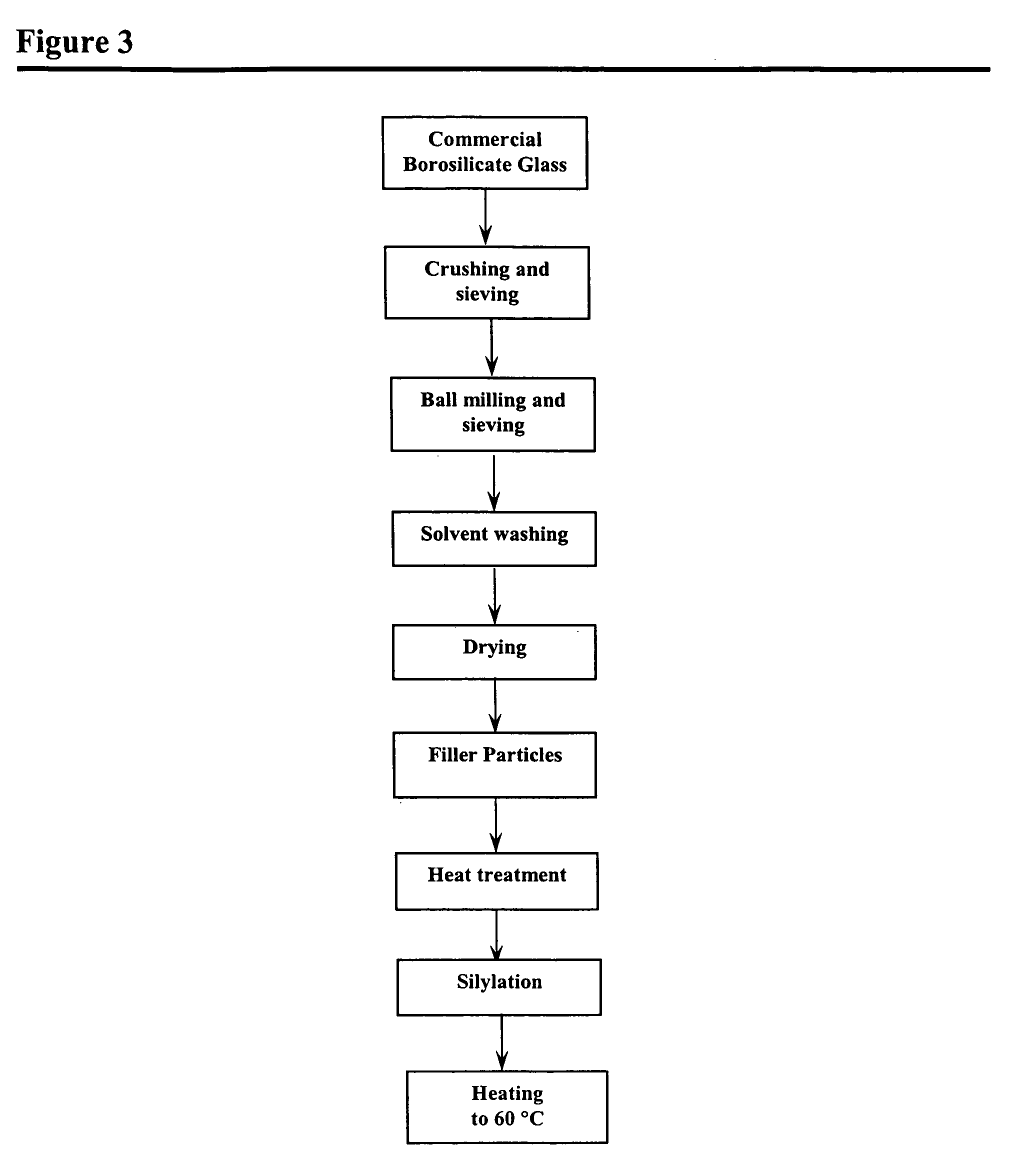
[0093] The process of preparing the glass filler particles is illustrated schematically by the flowchart depicted in FIG. 3. A commercial, alkali-free borosilicate glass sheet, marketed under the trademark AF45 by Schott Corporation, having an average refractive index of about 1.526 at about 588 nm and at about 25° C., and having a refractive index variation within the glass of less than about 0.001, is crushed into coarse particles and then sieved through a #8 mesh sieve to eliminate all particles larger than about 2.36 mm in diameter. These sieved particles are placed in a 100 ml zirconia milling jar, along with 3 milling balls having diameters of 20 mm and 15 milling balls having diameters of 15 mm. The particles then are planetary ball-milled at about 2...

example 2

Filler Size Between 1 μm and 100 μm

[0102] An encapsulant is prepared and analyzed in the same manner as in EXAMPLE 1, except that the filler particles remaining in the solvent used in the step of solvent washing are used as filler. These particles are recovered by filtration and drying of the solvent. As shown in FIG. 8, the sizes of these particles ranges between 1 μm and 100 μm, with a peak at about 10 μm, as determined by the particle size analyzer. About 60% by volume of this powder is composed of particles having sizes less than about 10 μm. Properties of the encapsulant, the filler, and the epoxy resin composition prepared in this example, are shown in Table 3. The transmittance of the resulting encapsulant is about 48% and within the scope of this present invention. The results from this example shows that the particles smaller than about 10 μm are agglomerated in the encapsulant, which leads to a decrease in the transmittance.

[0103] Taken together, the results of EXAMPLES ...

example 3

Higher Filler Amount

[0106] An encapsulant is prepared and analyzed in the same manner as in EXAMPLE 1, except that the filler amount in the encapsulant is about 46% by volume, instead of about 16% by volume. Properties of the encapsulant, the filler, and the epoxy resin composition prepared in this example are shown in Table 3. The transmittance of this encapsulant is about 79.2%. The average CTE is about 14.4 ppm / ° C., with a CTE variation less than about ±1%.

[0107] Taken together, EXAMPLES 1 and 3 demonstrate that a wide range of filler loading can be incorporated into the encapsulant while retaining high transmittance, thereby allowing adjustment of transmittance and CTE to meet varying requirements. Taken together, EXAMPLES 1 and 3 and COMPARATIVE EXAMPLES 3 and 4 demonstrate that the filler content of the encapsulants should be preferably between 5% and 60% by volume, more preferably between 10% and 50% by volume, and most preferably between 15% and 40% by volume, to obtain b...


PUM

PropertyMeasurementUnit
Temperatureaaaaaaaaaa
Lengthaaaaaaaaaa
Lengthaaaaaaaaaa

Abstract

An encapsulant is described for an optoelectronic device or optical component, which provides a coefficient of thermal expansion of less than 50 ppm/° C., with a variation of less than ±30%, and further provides an optical transmittance of at least 20% at a wavelength in the range of 400 to 900 nm, at an encapsulant thickness of about 1 mm. The encapsulant includes a filler consisting essentially of glass particles having diameters smaller than 500 μm, being essentially free of titania and lead oxide, and having a refractive index in the range of 1.48 to 1.60, with a variance of less than about 0.001. A method for making the encapsulant also is described, the method including steps of (1) processing the glass to form particles having diameters between 1 and 500 μm, (2) preparing an epoxy resin composition having at a cured stage a refractive index close to that of the glass filler particles, (3) mixing the epoxy resin composition with the filler particles to form a filled epoxy resin composition, (4) encapsulating an optoelectronic device with the filled epoxy resin composition, and (5) curing the filled epoxy resin composition.

Description

BACKGROUND OF THE INVENTION [0001] The present invention relates generally to encapsulants for optoelectronic devices and, more particularly, to such encapsulants exhibiting superior optical, thermo-mechanical, electrical, and environmental qualities. The present invention also relates to methods for making such encapsulants. [0002] Optical and electronic (i.e., “optoelectronic”) devices, such as LEDs, photodetectors, and fiber optic components, generally are encapsulated using a variety of materials to protect the devices from vibration, humidity, heat, environmental deterioration, electrical leakages, and other deteriorative factors. [0003] U.S. Pat. No. 3,547,871 to Hofman et al. describes a low coefficient of thermal expansion (“CTE”) encapsulant comprising an epoxy resin and a filler having a particle size ranging between 10 μm and 300 μm. This encapsulant resin has a viscosity below 20,000 cP, at 100° C. The filler is selected from silica, fused quartz, beryllium aluminum sili...

Claims


Application Information

Patent Timeline
IPC IPC(8): C08L63/00H01L21/56B32B27/38
CPCC08G59/226C08G59/4215C08G59/686C08K3/40C08K9/06C08L63/00H01L2924/0002H01L23/293H01L31/0203H01L2924/00Y10T428/31511
Inventor YAN, YONGANMEYERS, DOUGLASMORRIS, MARKMEIXNER, D. LAURENCERAYCHAUDHURI, SATYABRATA
Owner YAZAKI CORP
Why Eureka
Try Eureka