Vertical heat exchanger configuration for LNG facility

a heat exchanger and vertical technology, applied in the direction of indirect heat exchangers, liquefaction, lighting and heating apparatus, etc., can solve the problems of pipeline availability or capacity exceeding the deliverability of pipelines, pipelines that are not available or are impractical,

Active Publication Date: 2006-04-27
CONOCOPHILLIPS CO
View PDF16 Cites 46 Cited by
  • Summary
  • Abstract
  • Description
  • Claims
  • Application Information

AI Technical Summary

Benefits of technology

[0012] It is, therefore, an object of the present invention to provide a novel natural gas liquefaction system that allows more components to be fabricated off-site and then shipped to and assembled at the site of the LNG facility.

Problems solved by technology

It is desirable to operate the pipeline under a substantially constant and high load factor but often the deliverability or capacity of the pipeline will exceed demand while at other times the demand may exceed the deliverability of the pipeline.
The liquefaction of natural gas is of even greater importance when transporting gas from a supply source which is separated by great distances from the candidate market and a pipeline either is not available or is impractical.
Ship transportation in the gaseous state is generally not practical because appreciable pressurization is required to significantly reduce the specific volume of the gas.
Such pressurization requires the use of more expensive storage containers.
However, as the capacity and size of LNG facilities increases, certain complex components have become too large to construct off-site and then ship to the final destination.
However, as LNG facilities have continued to increase in capacity and size, the size of cold boxes has also increased.
In fact, some cold boxes are now too large to ship on standard ocean-going vessels.
Thus, newly-constructed high-capacity LNG facilities utilizing conventional horizontal core-in-kettle heat exchangers require the cold box to be assembled on-site because a pre-assembled cold box would be too large to ship on a standard ocean-going vessel.
In addition to the size / space problems posed by conventional horizontal core-in-kettle heat exchangers, a number of heat transfer inefficiencies can be associated with such horizontal core-in-kettle heat exchangers.
For example, the minimal liquid refrigerant depth provided below the core of the exchanger can hamper the availability of liquid refrigerant to the core.
Also, the vertical distance between the top of the core and the upper gaseous refrigerant outlet of the shell may be too small to provide adequate disengagement of the gaseous and liquid phases of the refrigerant.
When adequate liquid / gas disengagement above the core is not achieved, a significant amount of liquid refrigerant entrained in the upwardly-flowing gaseous refrigerant can undesirably exit the upper gaseous refrigerant outlet of the shell.

Method used


Image

  • Vertical heat exchanger configuration for LNG facility
  • Vertical heat exchanger configuration for LNG facility
  • Vertical heat exchanger configuration for LNG facility

Examples


Embodiment Construction

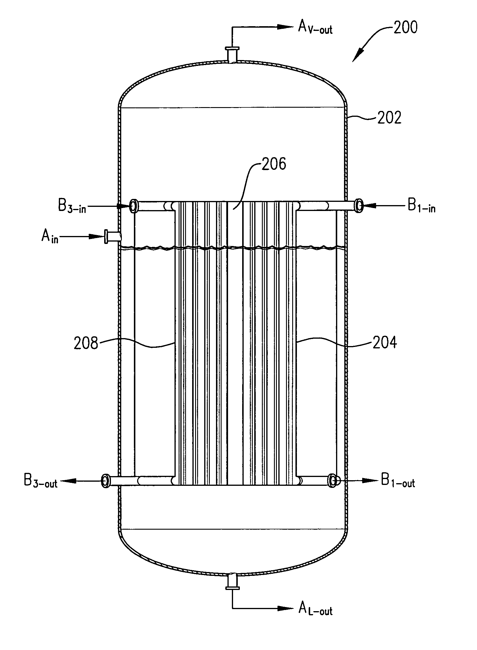
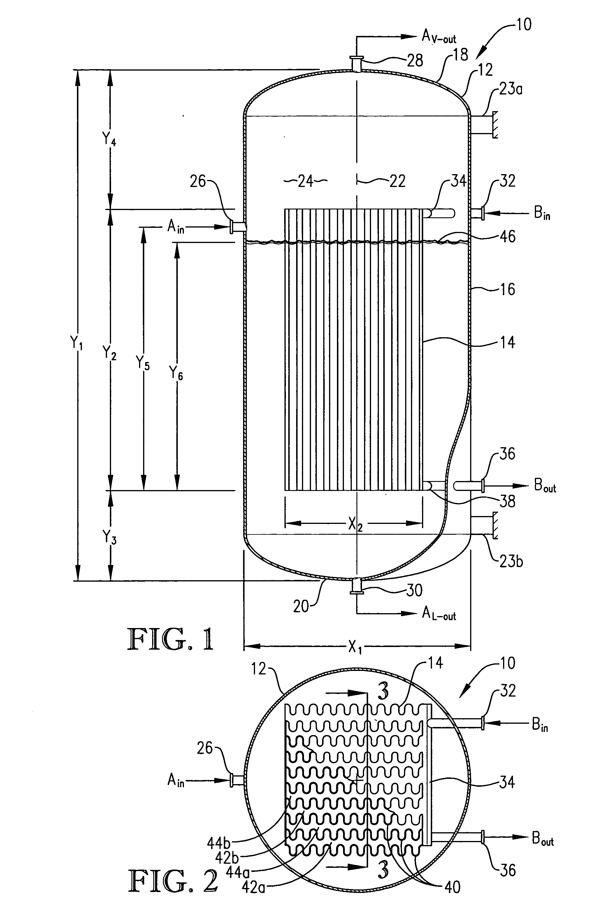
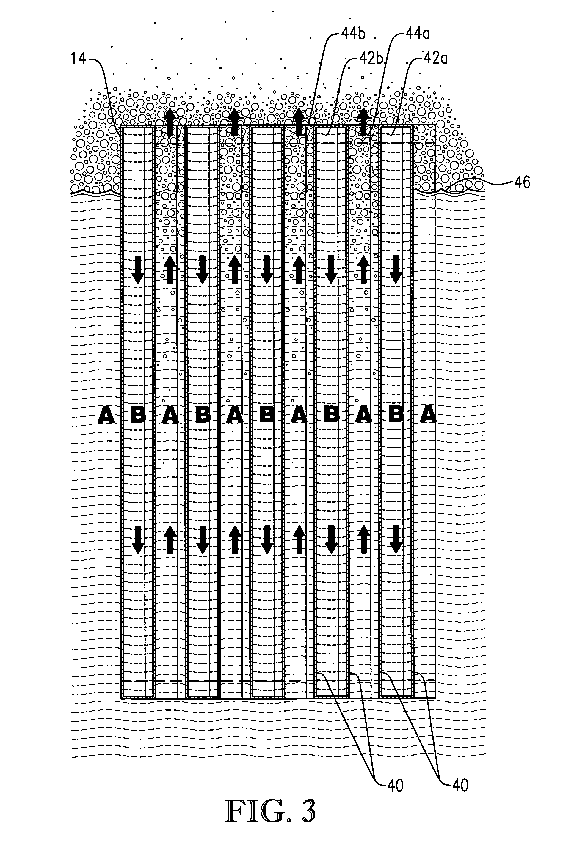
[0036] The present invention was conceived while searching for a solution to the above-described problems stemming from the need for increasingly large cold boxes in high-capacity LNG facilities. However, at least one embodiment of the present invention may find application outside the area of natural gas liquefaction. For example, although the vertical core-in-kettle heat exchanger designs depicted in FIGS. 1-9 are well suited for use in LNG processes / facilities, these heat exchangers exhibit enhanced efficiencies which make their implementation desirable for many other applications requiring indirect heat transfer.

[0037] Referring initially to FIG. 1, an inventive vertical core-in-kettle heat exchanger 10 is illustrated as generally comprising a shell 12 and a core 14. Shell 12 includes a substantially cylindrical sidewall 16, an upper end cap 18, and a lower end cap 20. Upper and lower end caps 18,20 are coupled to generally opposite ends of sidewall 16. Sidewall 16 extends alon...


PUM


Abstract

LNG facility employing one or more vertical core-in-kettle heat exchangers to cool natural gas via indirect heat exchange with a refrigerant. The vertical core-in-kettle heat exchangers save plot space and can be use to reduce the size of cold boxes employed in the LNG facility. In addition, vertical core-in-kettle heat exchangers can exhibit enhanced heat transfer efficiency due to improved refrigerant access to the core, improved refrigerant circulation around the core, and/or improved vapor/liquid disengagement above the core.

Description

BACKGROUND OF THE INVENTION [0001] 1. Field of the Invention [0002] This invention relates to a method and apparatus for liquefying natural gas. In another aspect, the invention concerns an improved method and apparatus for facilitating indirect heat transfer between a refrigerant and a cooled fluid. In still another aspect, the invention relates to a system for liquefying natural gas that employs at least one vertical core-in-kettle heat exchanger to cool the natural gas. [0003] 2. Description of the Prior Art [0004] The cryogenic liquefaction of natural gas is routinely practiced as a means of converting natural gas into a more convenient form for transportation and storage. Such liquefaction reduces the volume of the natural gas by about 600-fold and results in a product which can be stored and transported at near atmospheric pressure. [0005] Natural gas is frequently transported by pipeline from the supply source to a distant market. It is desirable to operate the pipeline under...

Claims


Application Information

Patent Timeline
Patent Type & Authority Applications(United States)
IPC IPC(8): F28D7/10F25B39/02F25J1/00F25J5/00
CPCF25J1/0022F25J1/0264F25J1/0052F25J1/0085F25J1/0087F25J1/0259F25J1/0262F25J2210/06F25J2220/64F25J2250/02F25J2250/20F25J2290/40F25J1/0258F25J1/021F25J5/005F25J1/004F25B39/02F25J1/00F25J5/00F28D7/10
Inventor EATON, ANTHONY P.MARTINEZ, BOBBY D.CHRISTIAN, MICHAEL
Owner CONOCOPHILLIPS CO
Why Eureka
Try Eureka