Method and apparatus for remotely controlling a welding system

Active Publication Date: 2006-04-27
ILLINOIS TOOL WORKS INC
View PDF19 Cites 54 Cited by
  • Summary
  • Abstract
  • Description
  • Claims
  • Application Information

AI Technical Summary

Benefits of technology

[0009] The present invention provides a system and method of remotely controlling operation of a welding machine via control commands transmitted across a weld cable connecting the welding machine to a peripheral, such as a wire feeder, that overcomes the aforementioned drawbacks.
[0010] A remote control uses a weld cable as a communication link to transfer control information to a welding power source. The information to be communicated to the power source includes welding power source output command information (amperage/voltage control), welding circuit on/off information (power source output contactor control), power source mode control (constant voltage/constant current), and the like. The control information may be transmitted in a serial communication and/or encoded using frequency and or voltage decoding. The control information may be transmitted during dedicated transmission intervals or as an offset to an OCV between the power source and wire feeder.
[0011] Therefore, in accordance with one aspect, the present invention inc

Problems solved by technology

A significant drawback to this control cable-based scheme is that the control cable is typically fragile relative to the welding cables designed to carry high currents at high voltages.
As such, the remote control cable can become damaged by being crushed or snagged from contact with surrounding machines and / or traffic.
This can cause damage to the wire feeder and / or the welding power source if internal power conductors become shorted to signal leads that are connected to sensitive signal level circuitry.
First, electric arc welding can create radio frequency interference that negatively affects the communication between a transceiver 9A of the wire feeder 2B and the transceiver 9B of the power source 4B.
Second, if the system is used inside metal structures such as tanks, ships, or large aircraft, the radio link can be lost due to the shielding effect of the metallic surroundings.
Third, if multiple welding stations use a radio link for remote control, each control loop would require a separate security code to prevent cross-talk or mis-transmission of control signals to the wrong welding machine.
By using pulse width modulated signals to remotely control operation of a power source, the amount of data as well as variability in the types of data that could be transmitted between the wire feeder and a power source is limited when compared to that which may be achieved with serialized or encoded communications.
As a result, absent a DC power supply, the wire feeder cannot be minimally powered so as to communicate with the power source to initiate the welding process.

Method used


Image

  • Method and apparatus for remotely controlling a welding system
  • Method and apparatus for remotely controlling a welding system
  • Method and apparatus for remotely controlling a welding system

Examples


Embodiment Construction

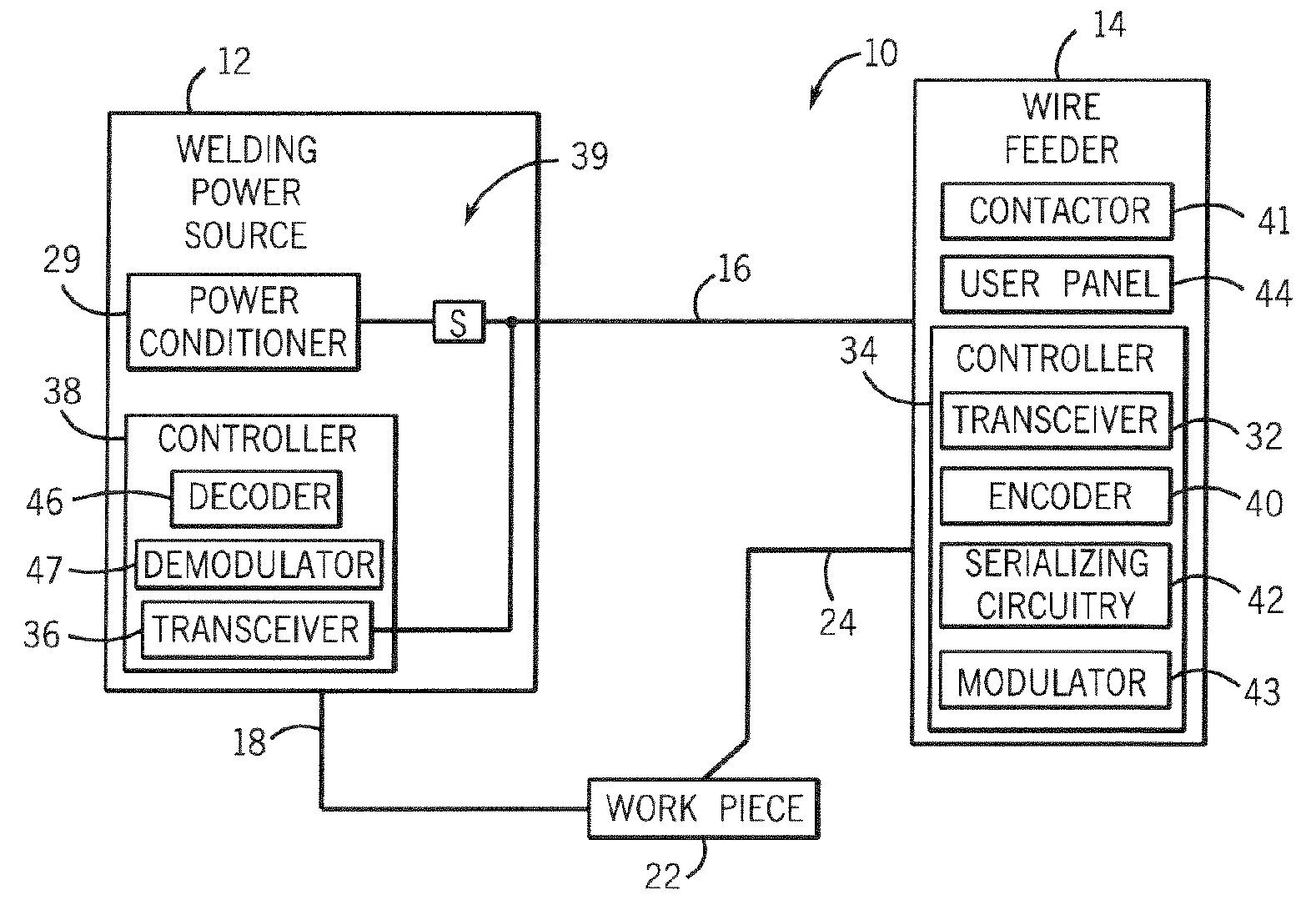
[0022] The present invention will be described with respect to regulation of a power source and a wire feeder of a MIG welding system based on feedback provided from a transceiver remote from the power source to a receiver incorporated within the power source. However, the present invention is equivalently applicable with power sources of TIG, stick, flux cored, and the like welding systems. Moreover, the present invention is also applicable with non-welding, high power systems such as plasma cutters and induction heaters.

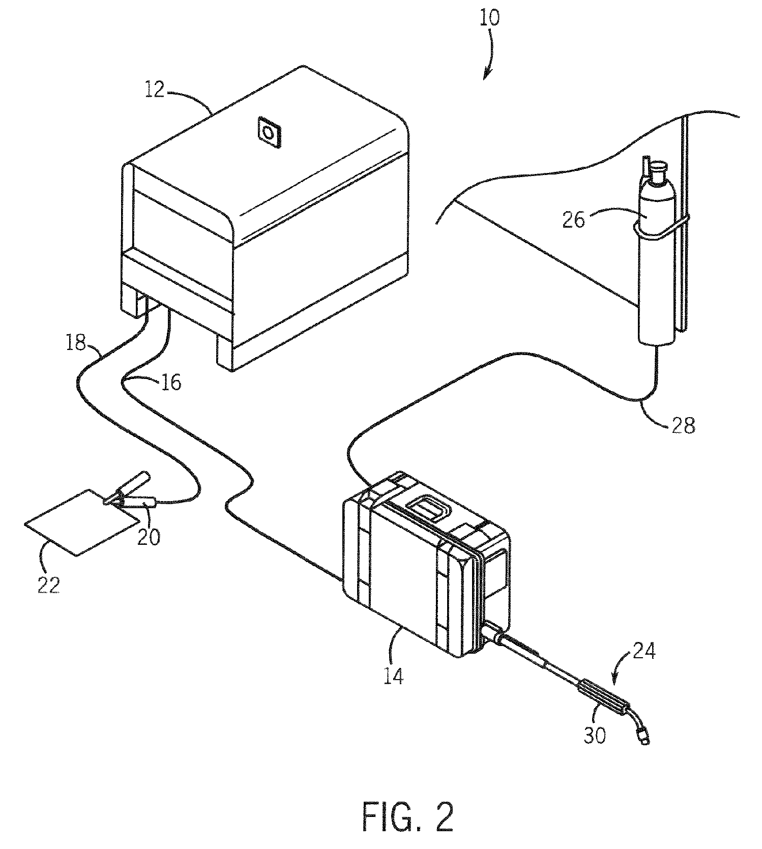
[0023] Referring to FIGS. 2 and 3, a MIG welding system 10 includes a welding power source 12 designed to supply power to a wire feeder 14 through a weld cable 16. The power source is designed to run in one of a number of modes including constant voltage (CV) and constant current (CC). Also connected to the power source is a secondary work weld cable 18 that connects the power source to a clamp 20 designed to receive cable 18 to workpiece 22. Also connected to wir...


PUM

PropertyMeasurementUnit
Poweraaaaaaaaaa
Currentaaaaaaaaaa
Electric potential / voltageaaaaaaaaaa

Abstract

The present invention is directed to a remote control that uses a welding circuit to transfer control information to a welding power source. The information to be communicated to the power source includes welding power source output command information (amperage / voltage control), welding circuit on / off information (power source output contactor control), and power source mode control (constant voltage / constant current). The control information may be transmitted in a serial communication and / or encoded using frequency and or voltage coding. The control information may be transmitted during dedicated transmission intervals or as an offset to an open circuit voltage between the power source and wire feeder.

Description

BACKGROUND OF THE INVENTION [0001] The present invention relates generally to welding machines and, more particularly, to a method and apparatus for remotely controlling operation of a power source of a welding-type system through the transmission of control signals across a weld cable. [0002] MIG welding, formerly known as Gas Metal Arc Welding (GMAW), combines the techniques and advantages of TIG welding's inert gas shielding with a continuous, consumable wire electrode. An electrical arc is created between the continuous, consumable wire electrode and a workpiece. As such, the consumable wire functions as the electrode in the weld circuit as well as the source of filler metal. MIG welding is a relatively simple process that allows an operator to concentrate on arc control. MIG welding may be used to weld most commercial metals and alloys including steel, aluminum, and stainless steel. Moreover, the travel speed and the deposition rates in MIG welding may be much higher than those...

Claims


Application Information

Patent Timeline
IPC IPC(8): B23K9/10
CPCB23K9/1087
Inventor ULRICH, JAMES F.
Owner ILLINOIS TOOL WORKS INC
Why Eureka
Try Eureka