Method of manufacturing a substrate with concave portions, a substrate with concave portions, a microlens substrate, a transmission screen, and a rear projection

a technology of concave portions and transmission screens, which is applied in the direction of lenses, instruments, other domestic objects, etc., can solve the problems of low light use efficiency of transmission screens provided with microlenses, interference of light passing through each of the microlenses with each other, and small vertical angle of view. , to achieve the effect of excellent angle of view characteristics

Inactive Publication Date: 2006-04-27
SEIKO EPSON CORP
View PDF1 Cites 10 Cited by
  • Summary
  • Abstract
  • Description
  • Claims
  • Application Information

AI Technical Summary

Benefits of technology

[0005] It is one object of the invention to provide a transmission screen and a rear projection which can prevent moire due to interference of light from being generated and have excellent angle of view characteristics.

Problems solved by technology

However, a conventional rear projection provided with such lenticular lenses has a problem that the vertical angle of view thereof is small although the lateral angle of view thereof is large (this is, there is a bias in the angles of view).
However, in such a transmission screen, since the transmission screen is provided with the microlens array sheet in which a plurality of microlenses are arranged in a square lattice manner, there has been a problem that light passing through each of the microlenses interferes with each other, and it is easy to generate moire compared with the case of using a lenticular lens, in particular.
Further, there has been problems that because the microlenses are arranged in the square lattice manner or the like, the light use efficiency of the transmission screen provided with the microlenses becomes low, the contrast thereof is made to become low, and a phenomenon in which the brightness of the transmission screen becomes drastically dark at a predetermined horizontal angle in the angle of view characteristics thereof (so-called, a certain-drawing phenomenon) is generated.

Method used


Image

  • Method of manufacturing a substrate with concave portions, a substrate with concave portions, a microlens substrate, a transmission screen, and a rear projection
  • Method of manufacturing a substrate with concave portions, a substrate with concave portions, a microlens substrate, a transmission screen, and a rear projection
  • Method of manufacturing a substrate with concave portions, a substrate with concave portions, a microlens substrate, a transmission screen, and a rear projection

Examples


example 1

[0179] A substrate with concave portions that was provided with a plurality of concave portions for forming microlenses was manufactured in the following manner.

[0180] First, a soda-lime glass substrate having a rectangle shape of 1.2 m (lateral)×0.7 m (longitudinal) and a thickness of 4.8 mm was prepared.

[0181] The soda-lime glass substrate was soaked in cleaning liquid containing 4% by weight ammonium hydrogen difluoride and 8% by weight sulfuric acid to carry out a 6 μm etching process, thereby cleaning its surface. Then, cleaning with pure water and drying with nitrogen (N2) gas (for removal of pure water) were carried out.

[0182] Next, a laminated structure of chromium / chromium oxide (that is, laminated structure in which a layer formed of chromium was laminated on the outer circumference of a layer formed of chromium oxide) was formed on one major surface of the soda-lime glass substrate by means of a spattering method. Namely, a mask and a back surface protective film each ...

example 2

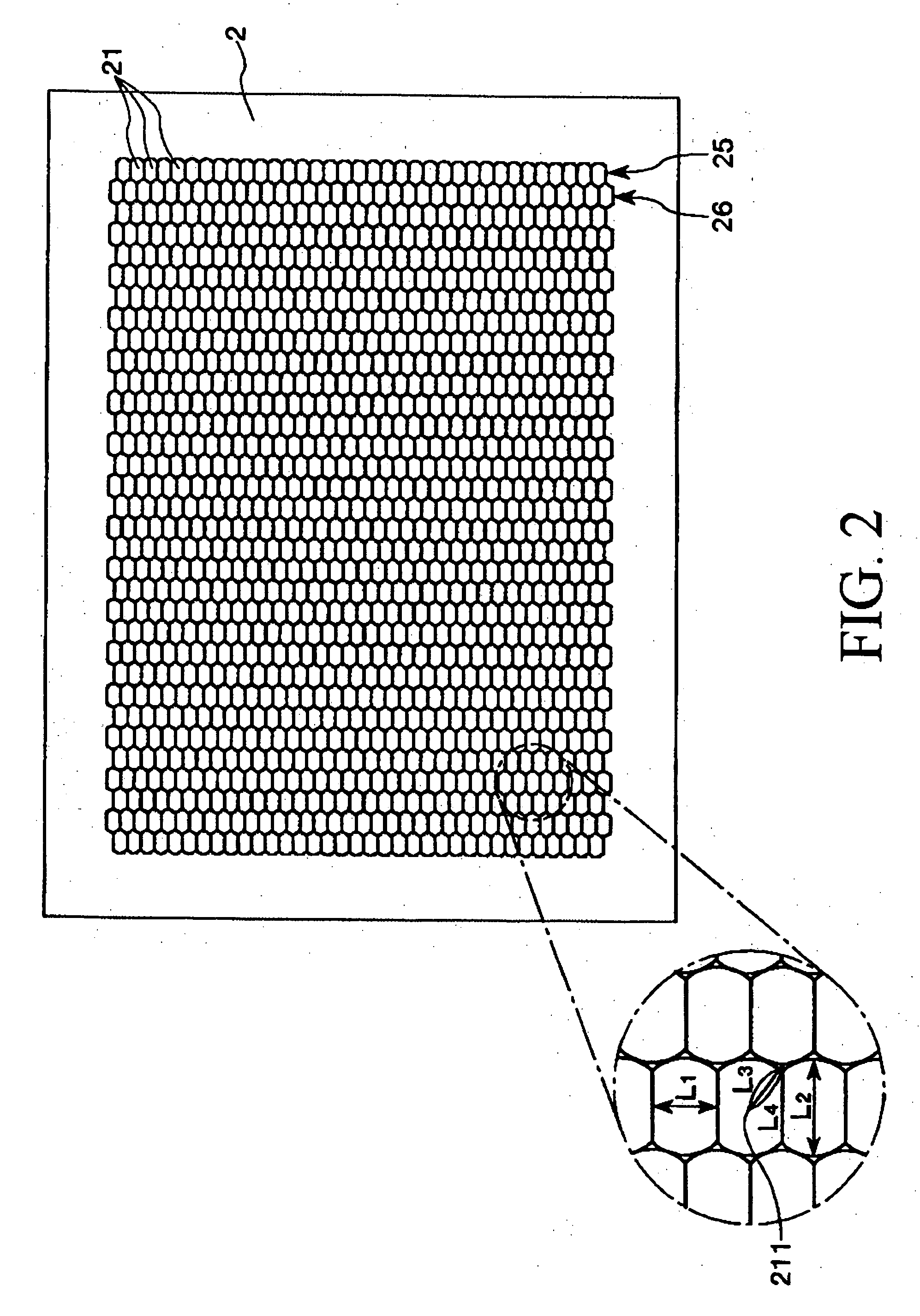
[0197] The shape and / or arrangement pattern of each of the concave portions in the substrate with concave portions were changed by appropriately changing irradiation conditions for the laser beams (that is, shape of each of the initial holes to be formed), and / or a soak time into an etchant. In this way, a main substrate was manufactured in the manner similar to that in Example 1 except that the shape and / or arrangement pattern of the microlenses to be formed in the microlens substrate were changed as shown in TABLE 1. In this case, by changing the size of each of spacers at this time, the thickness of the resin layer of the main substrate (portion except for the microlenses) was set to 0.005 mm.

[0198] Then, a positive type photopolymer to which a light shielding material (carbon black) was added (PC405G: made by JSR Corporation) was supplied onto the light emission surface of the main substrate (the surface opposite to the surface on which the microlenses had been formed) by means...

examples 3 to 11

[0205] A microlens substrate and a transmission screen were manufactured in the manner similar to those in Example 1 described above except that the shape of each of the concave portions and the arrangement pattern of the concave portions of the substrate with concave portions were changed by changing any of the configuration of the mask, the conditions of the irradiation with laser beams (that is, the shape of each of the initial holes to be formed and the depth of each of the initial concave portions) and the soaking time into the etchant, whereby the shape of each of the microlenses to be formed on the microlens substrate and the arrangement pattern of the microlenses were changed as shown in TABLE 1.


PUM


Abstract

A method of manufacturing a substrate 6 provided with a plurality of concave portions 61 is disclosed. The substrate 6 is used for manufacturing a microlens substrate provided with a plurality of microlenses as convex lenses which are to be formed using the plurality of concave portions 61. The method includes the steps of: preparing a base substrate 7, the base substrate 7 having two major surfaces; forming at least one layer on the one of the two major surfaces of the base substrate 7; forming a plurality of openings 81 in the at least one layer to form a mask 8, the diameter of each of the plurality of openings 81 being in the range of 0.8 to 20 μm; forming the plurality of concave portions 61 in the base substrate 7 by subjecting the base substrate 7 with the mask 8 on which the plurality of openings 81 have been formed to an etching process so that each of the formed concave portions 61 has a substantially elliptic shape; and removing the mask 8 from the base substrate 7 (6). In this case, the plurality of formed concave portions 61 are arranged on the base substrate 7 in a houndstooth check manner. Further, in the case where the depth of each of the formed concave portions 61 in a direction perpendicular to the major surface of the base substrate 7 is defined as D (μm) and the value obtained by dividing the difference between the length of each of the formed concave portions 61 in a long axis direction and the diameter of each of the formed openings 81 by two is defined as S (μm), then D and S satisfy the relation: 0.90≦S/D≦1.40. Moreover, a ratio of an area occupied by all the plurality of formed concave portions 61 in a usable area where the plurality of concave portions 61 are formed with respect to the entire usable area is 90% or more when viewed from above the one major surface of the base substrate 7.

Description

CROSS-REFERENCE TO RELATED APPLICATION [0001] This application claims priority to Japanese Patent Application No. 2004-307461 filed Oct. 21, 2004 and No. 2005-296935 filed Oct. 11, 2005, which are hereby expressly incorporated by reference herein in their entirety. FIELD OF THE INVENTION [0002] The present invention relates to a method of manufacturing a substrate with concave portions, a substrate with concave portions, a microlens substrate, a transmission screen, and a rear projection. BACKGROUND OF THE INVENTION [0003] In recent years, demand for a rear projection is becoming increasingly strong as a suitable display for a monitor for a home theater, a large screen television, or the like. In a transmission screen used for the rear projector, lenticular lenses are in general use. However, a conventional rear projection provided with such lenticular lenses has a problem that the vertical angle of view thereof is small although the lateral angle of view thereof is large (this is, ...

Claims


Application Information

Patent Timeline
Patent Type & Authority Applications(United States)
IPC IPC(8): H01L23/48G02B3/00G02B3/08G02B5/02G03B21/62
CPCB29D11/00278B29D11/00365G02B3/0012G02B3/0031G02B3/08G03B21/56G03B21/60
Inventor SHIMIZU, NOBUO
Owner SEIKO EPSON CORP
Why Eureka
Try Eureka