Brake control system

Inactive Publication Date: 2006-04-27
HITACHI LTD
View PDF7 Cites 27 Cited by
  • Summary
  • Abstract
  • Description
  • Claims
  • Application Information

AI Technical Summary

Benefits of technology

[0004] Accordingly, it is an object of the invention to provide an accumulatorless hydraulic brake control system capable of

Problems solved by technology

There is an increased tendency for the flow rate of brake fluid in the wheel-brake cylinder subjected to brake control to overshoot a desired value, in other words, there is a tendency for a rapid change in the flow rate of brake fluid supplied into the wheel cylinder to occur owing to the comparatively high accumulat

Method used


Image

  • Brake control system
  • Brake control system
  • Brake control system

Examples


1st embodiment

Comparison of Operation and Effects Between Earlier Brake Control System and Improved System of 1st Embodiment

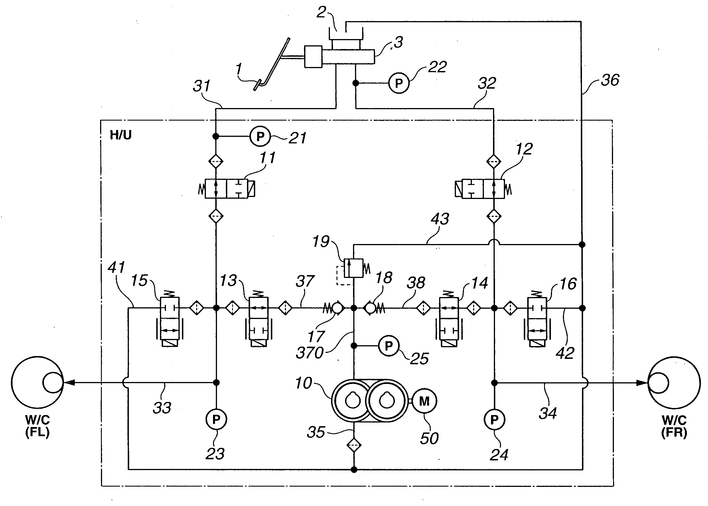
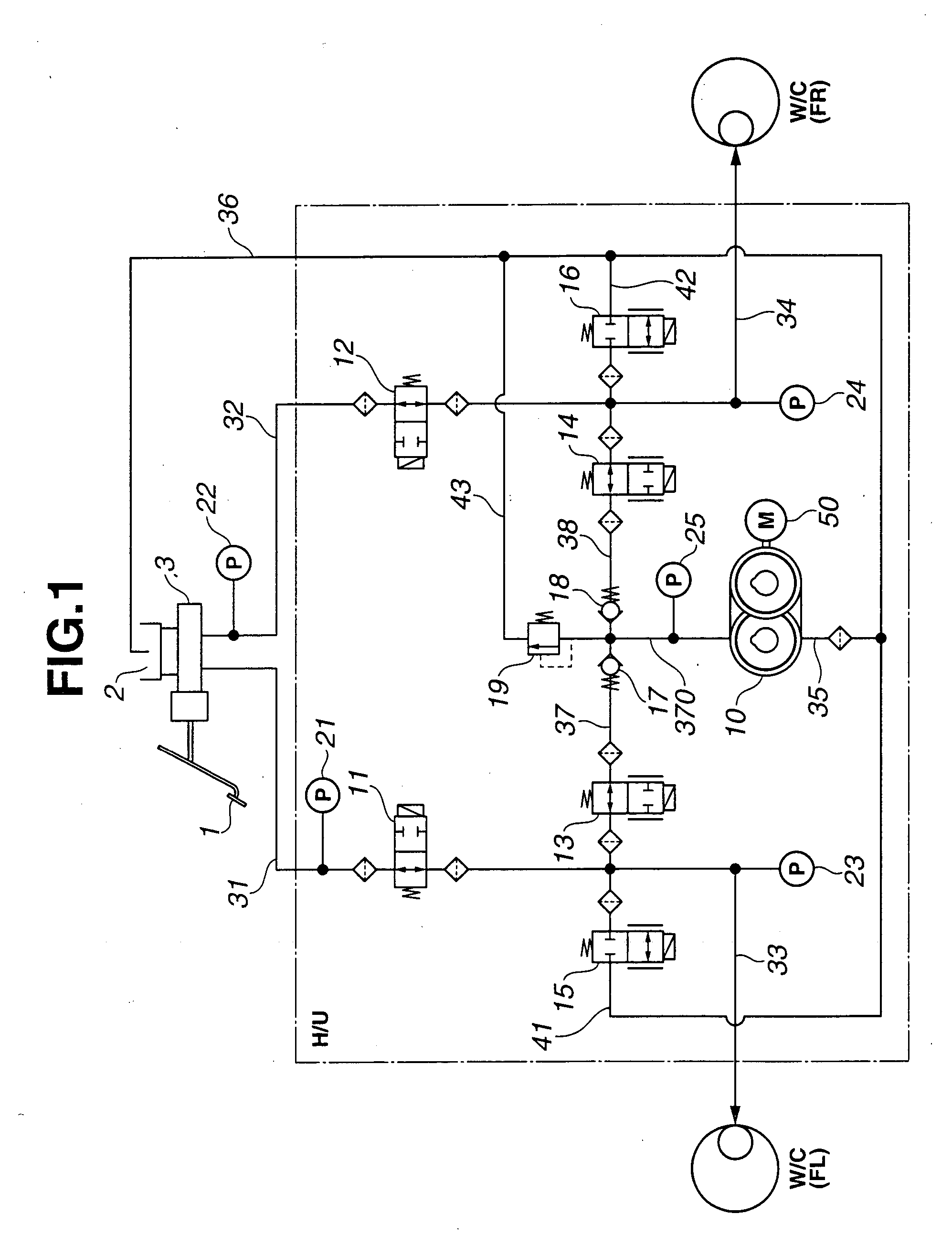
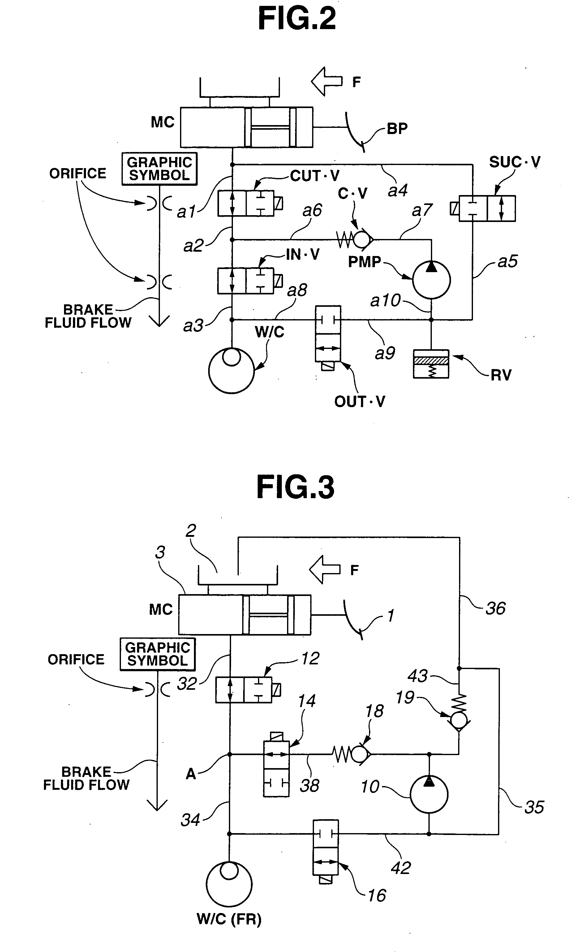
[0035] On earlier pressure-accumulator equipped hydraulic brake control systems, hydraulic pressure stored in a pressure accumulator is used to operate wheel brakes of the vehicle. To avoid the hydraulic pressure in the pressure accumulator from continuously acting on each of wheel-brake cylinders, normally-closed valves are disposed in hydraulic circuits between each individual wheel-brake cylinder inlet-and-outlet ports and the pressure accumulator. Only when the brakes must be applied, the normally-closed valves associated with the respective wheel-brake cylinders are opened for wheel-cylinder pressure application. The normally-closed valves also serve as back-flow prevention valve means that prevent the master-cylinder pressure from acting on the pressure accumulator side when the system failure occurs and thus manual braking action is required. However, owing to the use...


PUM


Abstract

In a brake control system for a vehicle employing a brake-by-wire (BBW) hydraulic control unit, a master cylinder serves as a first fluid pressure source and a pump serves as a second fluid pressure source operated during a BBW system normal brake operating mode. Also provided is a manual-brake hydraulic circuit capable of supplying hydraulic pressure from the master cylinder to the wheel-brake cylinder during a fail-safe operating mode. A back-flow prevention device is disposed in a pump outlet passage, intercommunicating the manual-brake hydraulic circuit and the pump outlet, for permitting free flow in one direction from the pump to the wheel cylinder. A normally-open inflow valve is disposed in the pump outlet passage downstream of the back-flow prevention device. A normally-open shutoff valve is disposed in the manual-brake hydraulic circuit upstream of the normally-open inflow valve, and unactuated and opened during the fail-safe operating mode.

Description

TECHNICAL FIELD [0001] The present invention relates to a brake control system for automotive vehicles, and specifically to an accumulatorless hydraulic brake control system of less wasteful energy consumption. BACKGROUND ART [0002] As is generally known, on automotive brake systems used to control braking torque (negative wheel torque) or wheel-brake cylinder pressure, it is more desirable to enhance a braking response to a demand for braking and also to provide an enhanced vehicle dynamics control performance or a stable vehicle dynamic behavior achieved by hydraulic brake control. On typical hydraulic brake systems, a pressure accumulator is often used to temporarily accumulate hydraulic pressure therein. The hydraulic pressure in the accumulator is fed or supplied to wheel-brake cylinders to operate the brakes of the automotive vehicle. One such pressure-accumulator equipped hydraulic brake system has been disclosed in Japanese Patent Provisional Publication No. 2000-168536 (her...

Claims


Application Information

Patent Timeline
IPC IPC(8): B60T13/74
CPCB60T8/3655B60T8/4031B60T8/4072B60T8/4081B60T8/4872B60T13/161B60T2201/12
Inventor KAJIYAMA, KEIGONAKAZAWA, CHIHARU
Owner HITACHI LTD
Why Eureka
Try Eureka