
Autostereoscopic 3D display device and fabrication method thereof

a display device and autostereoscopic technology, applied in the field of display devices, can solve the problems of complicated fabrication process, inconvenient wearing eyeglasses, and difficulty for the viewer to observe other objects, and achieve the effect of light weight and simple fabrication process

Active Publication Date: 2006-04-27
LG DISPLAY CO LTD
View PDF7 Cites 52 Cited by
  • Summary
  • Abstract
  • Description
  • Claims
  • Application Information

AI Technical Summary

Benefits of technology

[0016] An object of the present invention is to provide an autostereoscopic 3D display device and a fabrication method thereof having a simple fabrication process
[0017] Another object of the present invention is to provide an autostereoscopic 3D display device that is thin and light weight and a fabrication method thereof.

Problems solved by technology

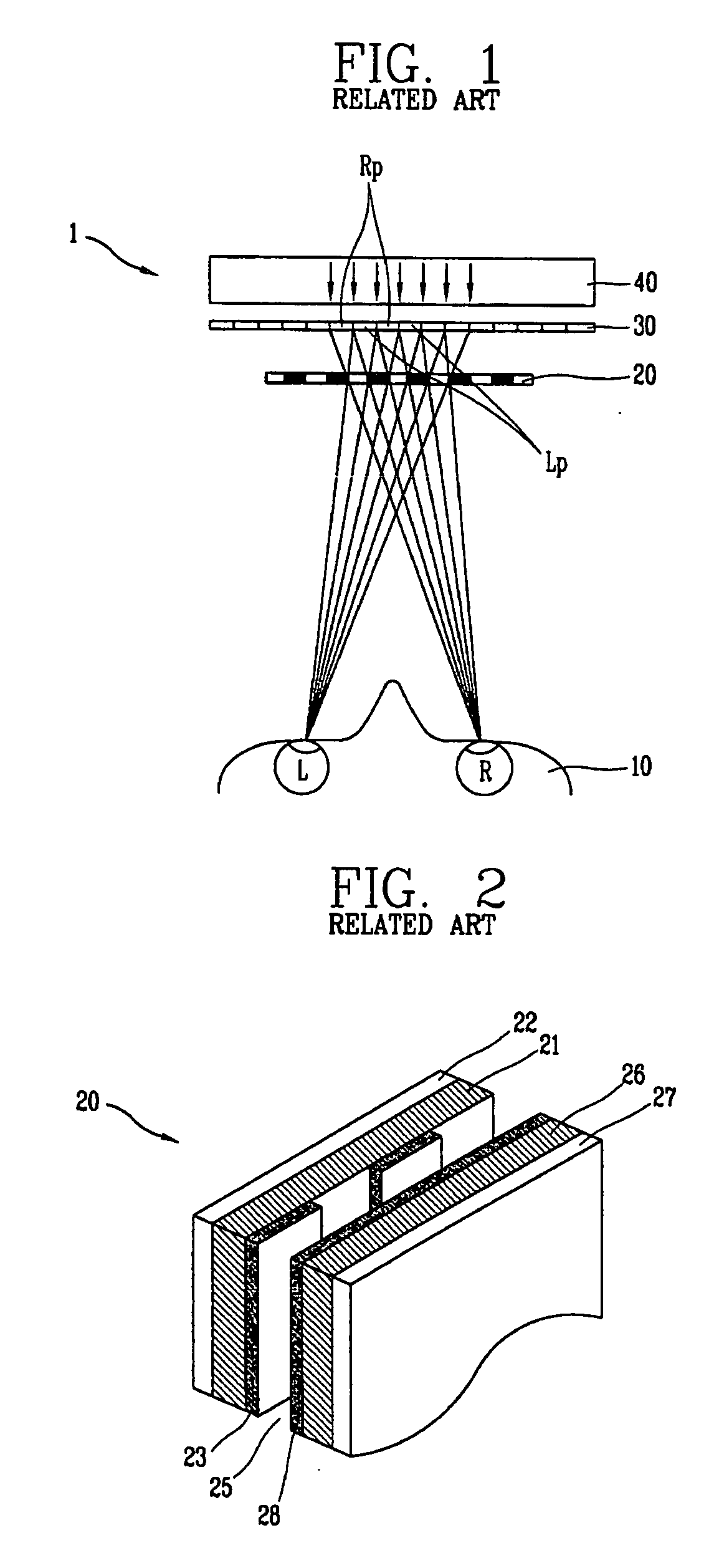
However, wearing eye-glasses is inconvenient and makes it difficult for the viewer to observe other objects in addition to the 3D image.
However, when a liquid crystal display panel is used as the switching panel as described, the fabrication process becomes complicated since a process of fabricating the LCD panel and a process of mounting the fabricated LCD panel onto the polarization plate and the display panel are required.
Thus, productivity is deteriorated.
In addition, as the autostereoscopic 3D display increases in size due to the addition of the LCD panel, it is hard to obtain an autostereoscopic 3D display device that is thin and light weight.
The addition of the LCD panel increases the unit cost of production and prevents mass production.

Method used


Image

  • Autostereoscopic 3D display device and fabrication method thereof
  • Autostereoscopic 3D display device and fabrication method thereof
  • Autostereoscopic 3D display device and fabrication method thereof

Examples


Embodiment Construction

[0032] Reference will now be made in detail to the preferred embodiments of the present invention, examples of which are illustrated in the accompanying drawings. Hereinafter, an autostereoscopic 3D display device and a fabrication method thereof will be described in more detail with reference to the accompanying drawings.

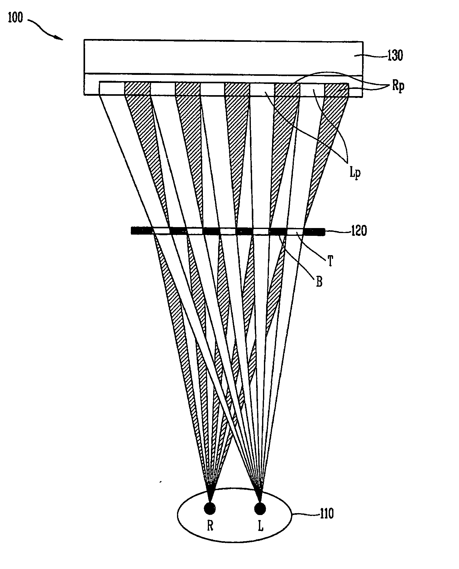
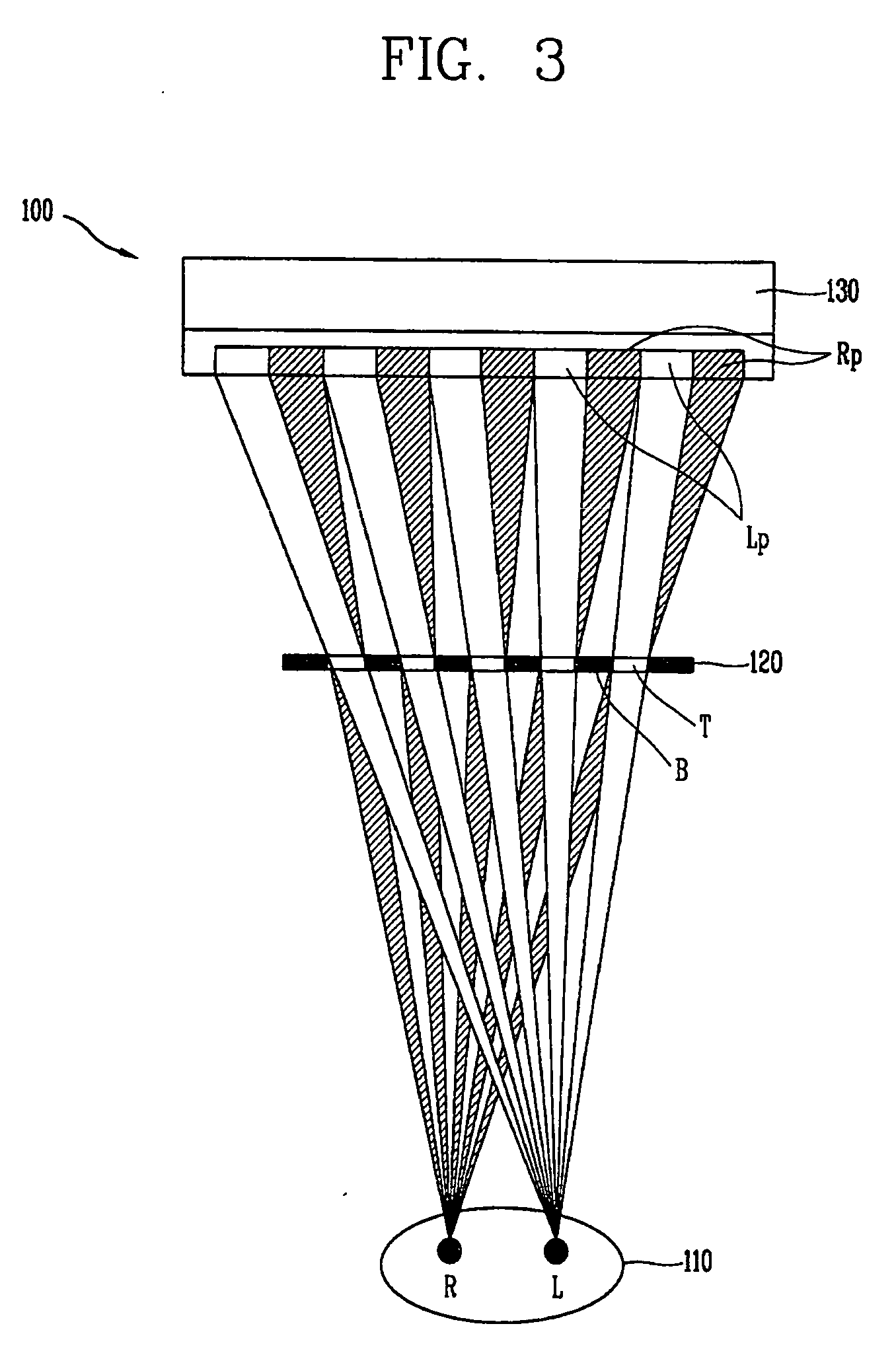
[0033]FIG. 3 is a schematic view illustrating an autostereoscopic 3D display device in accordance with the present invention. As illustrated therein, in an autostereoscopic 3D display device 100, a switching panel 120—in which a transmission region (T) and a non-transmission region (B) are repetitively arranged—is disposed in front of a display panel 130. The switching panel 120 may also be formed at the rear of the display panel 130.

[0034] The display panel 130 may be one of an LCD (liquid crystal display) panel, a PDP (plasma display panel) panel, an FED (field emission display) panel, an EL (electric luminescence) panel, and a VFD (vacuum fluorescent display) ...


PUM


Abstract

An autostereoscopic 3D display device is provided. The display device includes a display panel for displaying an image, and a switching panel attached to the display panel for selectively implementing a 3D image mode and a 2D image mode according to whether an electric signal is supplied. The switching panel is divided into a transmission region and a non-transmission region using electrochromic materials.

Description

[0001] This application claims the benefit of Korean Patent Application No. 2004-0085129 filed in Korea on Oct. 23, 2004, which is hereby incorporated by reference. BACKGROUND OF THE INVENTION [0002] 1. Field of the Invention [0003] The present invention relates to a display device, and more particularly, to a thin and light autostereoscopic 3D display device that selectively switches between a 3D image mode and a 2D image mode. [0004] 2. Description of the Related Art [0005] People perceive a three-dimensional effect because of physiological and psychological factors. In general, autostereoscopic 3D display techniques using binocular parallax, the largest factor in producing autostereoscopic viewing of an object at a short distance, permits people to achieve autostereoscopic viewing of an object. Techniques for displaying a 3D image are generally divided into those in which viewers wear a pair of eye-glasses and those in which viewers do not wear a pair of eye-glasses. [0006] The t...

Claims


Application Information

Patent Timeline
IPC IPC(8): G09G5/00G02B30/30
CPCG02B27/2214H04N13/0454H04N13/359G02B30/30G02F1/13G02B30/27
Inventor CHEN, BYUNG-SOONKIM, HYEOK-SOO
Owner LG DISPLAY CO LTD
Learn More