Welding joint of fuel tank

a fuel tank and welding joint technology, applied in the direction of hose connection, manufacturing tools, transportation and packaging, etc., can solve the problems of insufficient fuel-permeability resistance, severe regulation of the permeability of the fuel to the exterior through the hose, and inherent problems, etc., to achieve easy fusion welding and integration, heightened fuel-permeability resistance in the whole welding joint, and superior fusion welding. the effect of welding strength

Inactive Publication Date: 2006-04-27
SUMITOMO RIKO CO LTD
View PDF2 Cites 15 Cited by
  • Summary
  • Abstract
  • Description
  • Claims
  • Application Information

AI Technical Summary

Benefits of technology

[0065] In this way, a fuel permeability resistance in the whole welding joint can be heightened still more.
[0066] According to the seventh aspect of the invention, the fusion-welded portion is fusion-welded to an end face defining an opening of the fuel tank. In this way, the problem can also be solved that the fuel gas within the fuel tank permeates out through the opening and the outer layer.
[0067] According to the eighth aspect of the invention, the welding joint furt

Problems solved by technology

In recent years, however, the permeability of the fuel to the exterior through the hose has been severely regulated from the viewpoint of the preservation of the environment.
Anyway, in a case where the connection portion for the tube is constructed by fusion-welding and integrating the resin-made welding joint to the resin-made fuel tank, problems as stated below are inherent.
However, although the HDPE resin has an excellent fusion-weldability to the fuel tank, it exhibits an insufficient fuel-permeability resistance to incur the problem that fuel permeates out of the welding joint.
As another problem, the HDPE is not sufficient in the point of sag resistance, and when this HDPE has undergone a strong tightening force from t

Method used


Image

  • Welding joint of fuel tank
  • Welding joint of fuel tank
  • Welding joint of fuel tank

Examples


Embodiment Construction

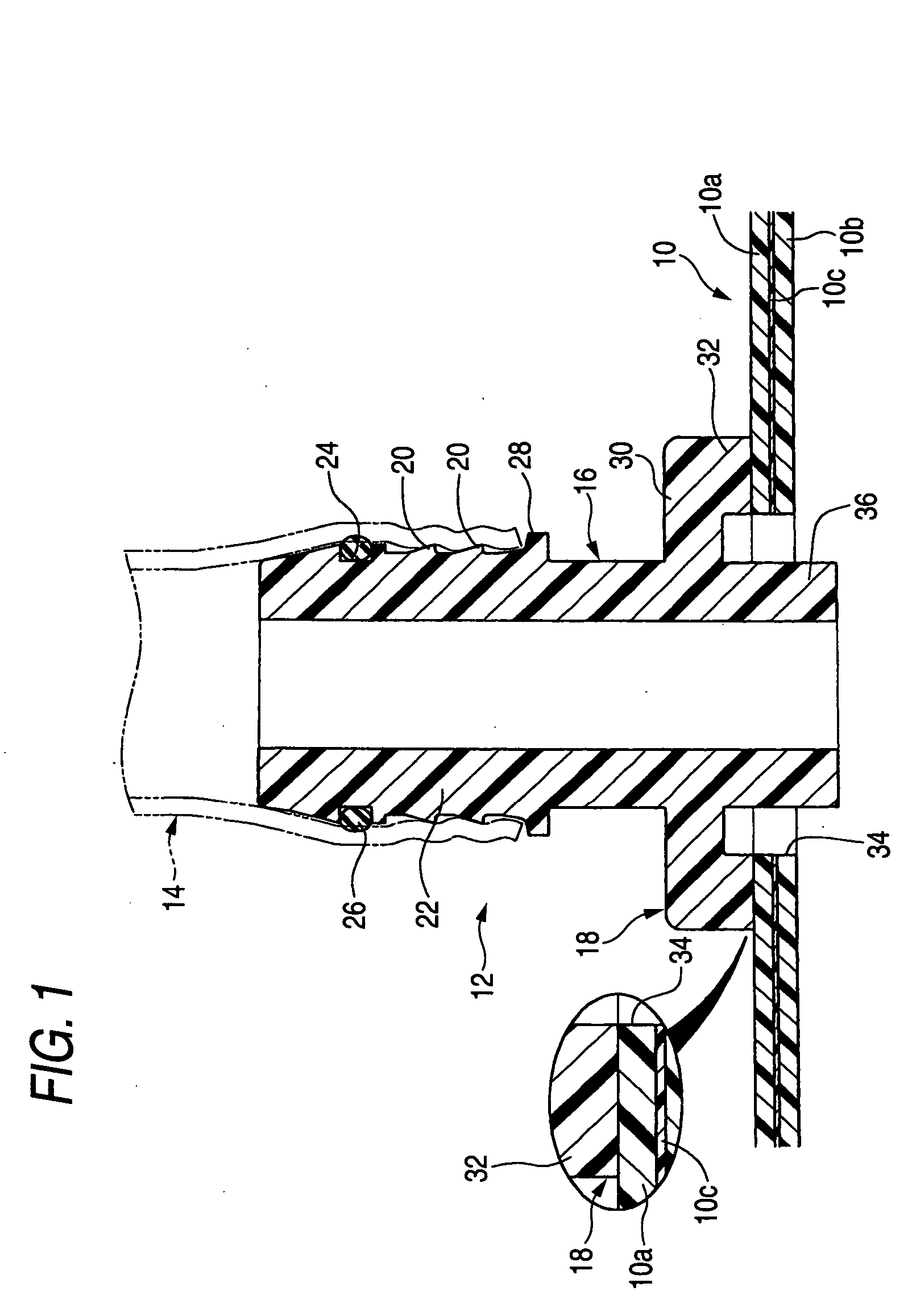
[0085] Now, embodiments of the present invention will be described in detail with reference to the drawings.

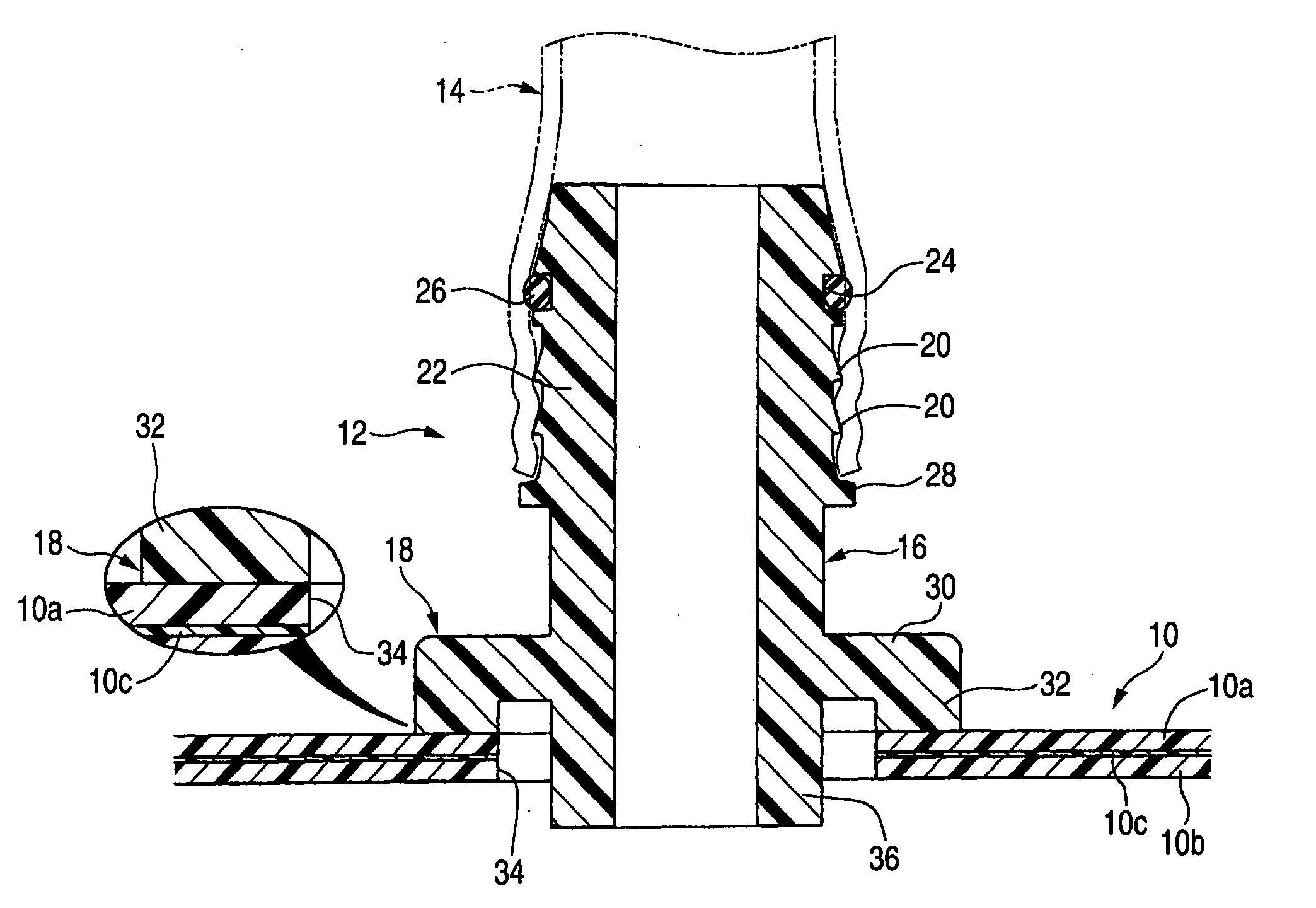
[0086] Referring to FIGS. 1 and 3, numeral 10 designates a resin-made fuel tank. Here, the fuel tank 10 forms a stacked structure which consists of an outer layer 10a, an inner layer 10b made of an HDPE resin, and a barrier layer (intermediate layer) 10c being thin.

[0087] Here, the barrier layer 10c is made of an EVOH resin which is excellent in fuel permeability resistance.

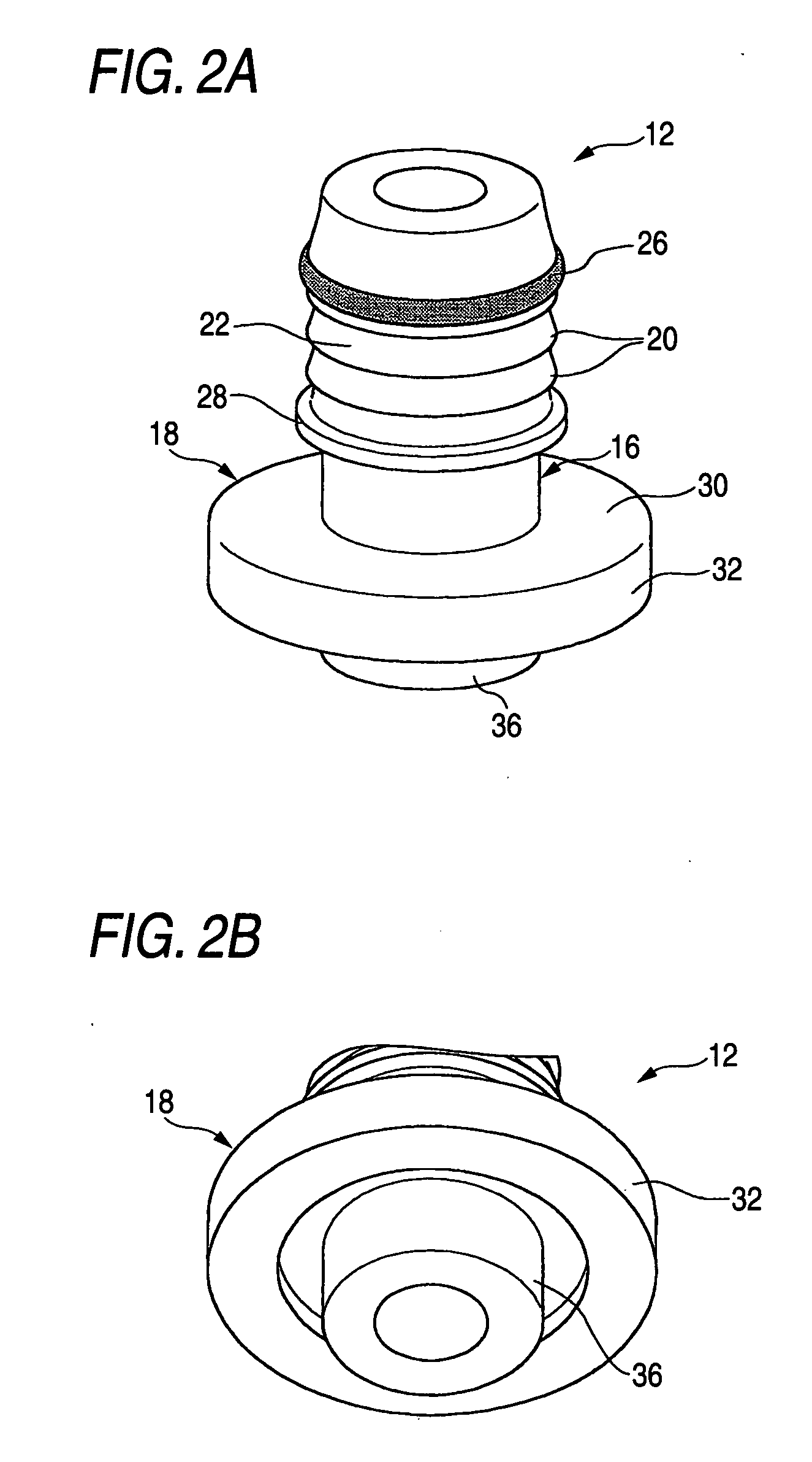
[0088] Numeral 12 designates a resin-made welding joint, which includes a cylindrical portion 16 serving as a connection portion for a piping tube (hereinbelow, simply termed “tube”) 14, and a fusion-welded portion 18 lying at the base end part of this welding joint.

[0089] The tube 14 is press-fitted onto the cylindrical portion 16 in an externally fit state, and it is connected to the fuel tank 10 through such a welding joint 12.

[0090] The outer peripheral surface of the cylindrical portion 16 is prov...


PUM


Abstract

A welding joint has a cylindrical portion being a connection portion and an annular fusion-welded portion disposed at a base end part of the cylindrical portion, the fusion-welded portion being configured to be thermal fusion welded to a resin-made fuel tank. At least parts of the fusion-welded portion and the cylindrical portion are integrally molded by employing a resinous alloy material in which a modified high-density polyethylene obtained by introducing a functional group of high affinity to a hydroxyl group of ethylene-vinylalcohol copolymer is alloyed with the ethylene-vinylalcohol copolymer singly or together with high-density polyethylene.

Description

BACKGROUND OF THE INVENTION [0001] 1. Field of the Invention [0002] This invention relates to a resin-made joint for connecting a piping tube or a connector to a resin-made fuel tank, and more particularly to a resin-made welding joint which is fusion-welded to a fuel tank so as to construct a connection portion. [0003] 2. Description of the Related Art [0004] A fuel tank which is mounted on an automobile is integrally provided with a joint that serves to connect a tube, a connector or the like for introducing fuel poured from a filler opening, into the fuel tank. [0005] Here, in case of, for example, the tube which introduces the fuel from the filler opening into the fuel tank, a rubber-made tube (rubber hose) has hitherto been employed. In recent years, however, the permeability of the fuel to the exterior through the hose has been severely regulated from the viewpoint of the preservation of the environment. Therefore, a rubber / resin compound tube in which the rubber hose further ...

Claims


Application Information

Patent Timeline
IPC IPC(8): F16B11/00
CPCB60K15/01B60K15/03177B60K2015/03453Y10T403/478F16L41/084Y10T403/477F16L33/30
Inventor NISHIYAMA, TAKAHIROSASAI, KENSUKEKATAYAMA, KAZUTAKAITO, HIROAKINIKI, NOBUAKISUZUKI, JUNICHIRO
Owner SUMITOMO RIKO CO LTD
Why Eureka
Try Eureka