

Low thermal resistance LED package
- Summary
- Abstract
- Description
- Claims
- Application Information
AI Technical Summary
Benefits of technology
Problems solved by technology
Method used
Image

Examples
second embodiment
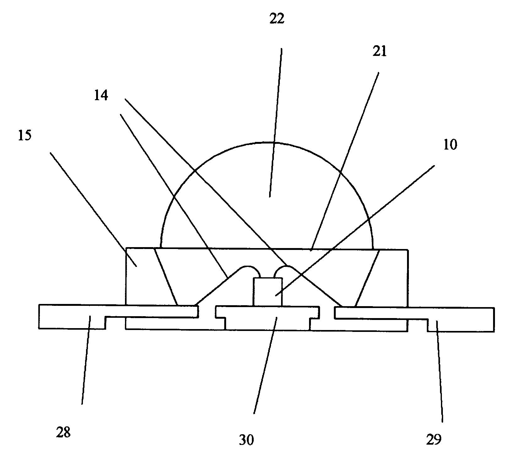
[0031]FIG. 6 shows the present invention. The structure is similar to that in FIG. 5, except that the three 0.5 mm metal sections are further half-etched from the bottom to from a positive lead frame 28, a negative lead frame 29 and a LED chip submount 30. The half-etched sections 28, 29 and 30 let the binding glue 15 to flow under half-etched sections to solidify the structure. Other elements with same reference numerals correspond to the same functions as that in FIG. 5.
third embodiment
[0032]FIG. 7 shows the present invention. A 0.5 mm thick metal sheet is punched out into five isolated sections: three positive lead frames 48, a negative lead frame 49, and a submount 40 for three color LEDs 10 which emit red, green and blue color lights. A glue is used to bind the five sections together and to form a cup with portions of the lead frames 48, lead 49 and the top of the submount 40 exposed, as shown in the cross-sectional view FIG. 8. The three LED chips 10 are mounted on the submount 40 and wire bonded with bonding wires 14 to respective positive lead frames 48 and common negative lead frame 49. Otherwise, the structure is similar to that in FIG. 6. Silicone 21 is used to fill the cup so as to cover and LED chips 10 and to protect the bonding wires 14. A convex lens is mounted over the silicone 21.
fourth embodiment
[0033]FIG. 9 shows the present invention. The structure is similar to that in FIG. 6 except that a back-to-back Zener diode 23 has been added for electric static protection. In this FIG. 8, the lead frame 58 corresponds to lead frame 28 in FIG. 6; lead frame 59 corresponds to lead frame 29; and lead frame 58 also corresponds to lead frame 30 in FIG. 6 in that this positive lead frame also serves as a connection to a terminal for the Zener diode 23. The other terminal of the Zener diode 23 is wire bonded to lead frame 59. Thus the Zener diode 23 is connected in parallel with the LED10. The elements with the same numerals correspond to the same functions as that in FIG. 6.
PUM
 Abstract
Description
Claims
Application Information