Brake system

a technology of brake system and braking force, which is applied in the direction of brake control system, brake system, vehicle components, etc., can solve the problem that the braking force generated in the case of abnormalities is not always sufficien

Inactive Publication Date: 2006-05-04
HONDA MOTOR CO LTD
View PDF11 Cites 19 Cited by
  • Summary
  • Abstract
  • Description
  • Claims
  • Application Information

AI Technical Summary

Benefits of technology

[0007] The present invention has been accomplished under the above-mentioned circumstances. It is an object thereof to provide a brake-by-wire type brake system that can generate a braking force that...

Problems solved by technology

When there is an abnormality in which the electrically operated fluid pressure outputting device becomes inoperative, the fail-safe solenoid switch valve is opened, and the disk brake system is actuated by brake fluid pressure generated by the master cy...

Method used


Image

  • Brake system
  • Brake system
  • Brake system

Examples


first embodiment

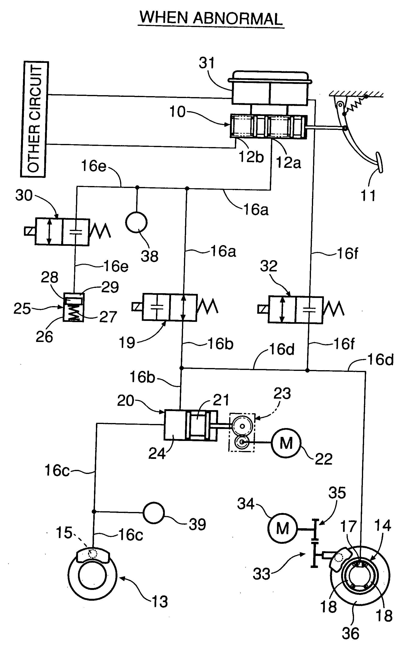
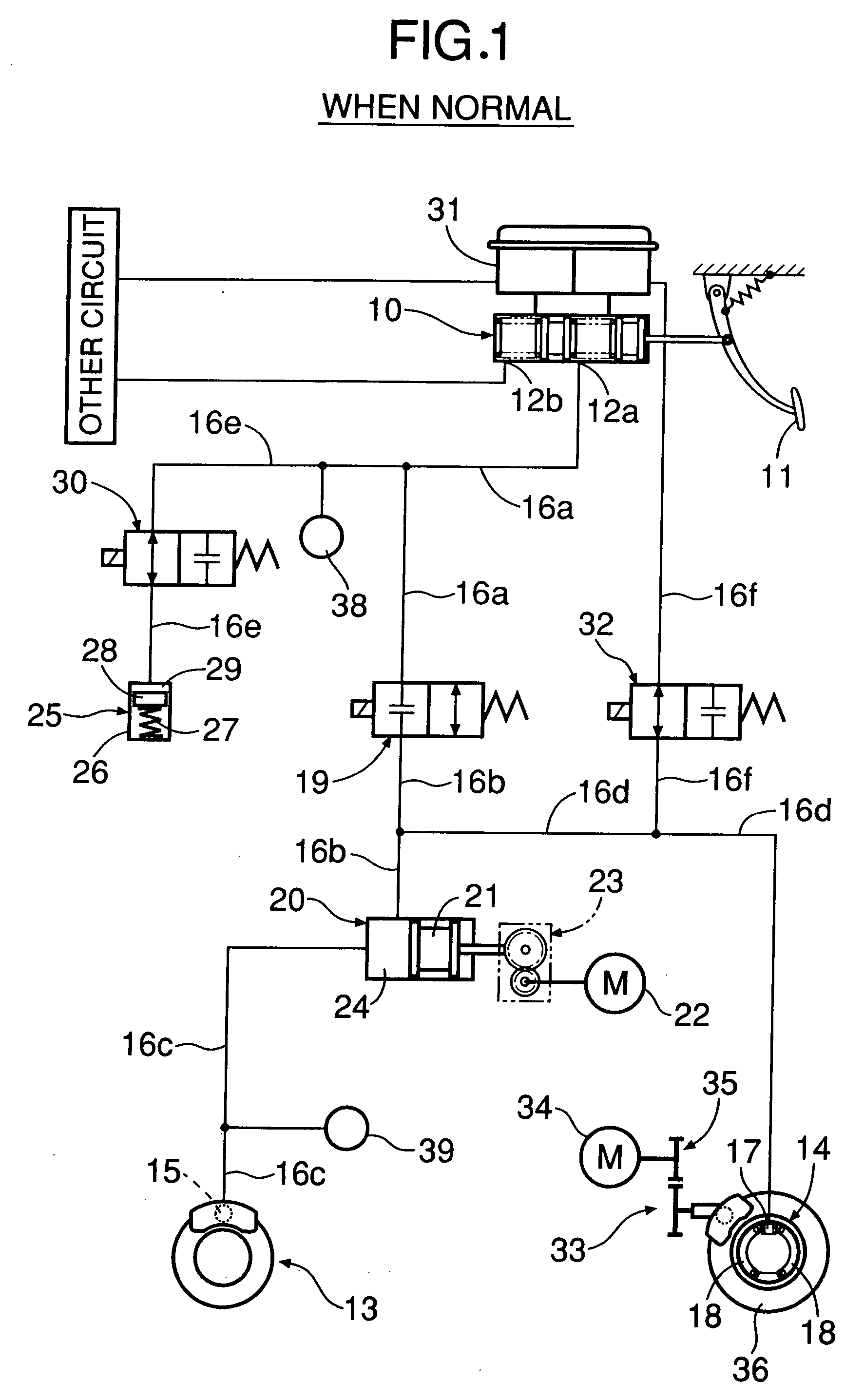
[0026]FIG. 1 and FIG. 2 show the present invention. As shown in FIG. 1, a tandem master cylinder 10 includes first and second output ports 12a and 12b for outputting a brake fluid pressure corresponding to a depressing force with which a driver depresses a brake pedal 11. The first output port 12a is connected to, for example, a disk brake system 13 of a front left wheel and a drum brake system 14 of a rear right wheel. The second output port 12b is connected to, for example, a disk brake system of a front right wheel and a drum brake system of a rear left wheel. FIG. 1 shows only one brake circuit connected to the first output port 12a, and the other brake circuit connected to the second output port 12b is not illustrated, but the structures of both brake circuits are substantially the same. The brake circuit connected to the first output port 12a is explained below.

[0027] The first output port 12a of the master cylinder 10 and a first wheel cylinder 15 of the disk brake system 13 ...

second embodiment

[0047] Also in the second embodiment, in the case of an abnormality in brake operation, not only the front wheel but also a rear wheel are braked by the brake fluid pressure generated by the master cylinder 10, thus reliably stopping the vehicle, and moreover, since a drum brake system 14 having a high braking function is employed for the rear wheel, the vehicle can be more reliably stopped.

third embodiment

[0048] the present invention is now explained by reference to FIG. 5 and FIG. 6.

[0049] The third embodiment is a modification of the first embodiment. Whereas in the first embodiment the electric braking device 33 of the rear wheel directly brakes the brake disk 36 by device of the driving force of the electric motor 34, in the third embodiment the second wheel cylinder 17 for driving brake shoes 18 of a drum brake system 14 is operated by brake fluid pressure generated by a motor cylinder 41 driven by an electric motor 34 via a reduction mechanism 40.

[0050] The electric motor 34 for driving the motor cylinder 41 of a rear wheel is controlled so that a fluid pressure detected by a fluid pressure sensor 45 coincides with a fluid pressure detected by a fluid pressure sensor 38.

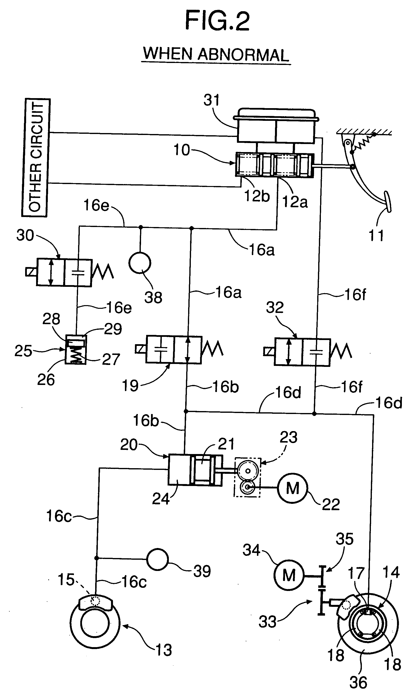
[0051] Also in the third embodiment, in the case of an abnormality in brake operation shown in FIG. 6, not only a front wheel but also the rear wheel are braked by brake fluid pressure generated by a master cy...


PUM


Abstract

During normal operation in which an electric braking device is operative, when a depressing force cut-off valve is closed and communication between a master cylinder and a disk brake system of a front wheel is cut off, the front wheel is braked by a brake pad directly driven by drive force of the electric braking device. When there is an abnormality in which the electric braking device breaks down, a wheel cylinder of a drum brake system of a rear wheel is operated by brake fluid pressure generated by the master cylinder operated by a driver's braking operation. Thus, since the drum brake system having a high braking function is operated in case of abnormality, the braking force is higher than the braking force during normal operation, thereby reliably stopping the vehicle.

Description

CROSS-REFERENCE TO RELATED APPLICATIONS [0001] The present invention claims priority under 35 USC 119 based on Japanese patent application No. 2004-302498, filed on Oct. 18, 2004. The subject matter of this priority document is incorporated in its entirety by reference herein. BACKGROUND OF THE INVENTION [0002] 1. Field of the Invention [0003] The present invention relates to a brake system in which during normal operation a wheel is braked by electric braking device. When there is an abnormality in which the electric braking device becomes inoperative, a wheel is braked using brake fluid pressure generated by a master cylinder actuated by a driver's braking operation. [0004] 2. Description of the Related Art [0005] A so-called brake-by-wire type brake system is known from Japanese Patent Publication No. 3205570 in which, during normal operation, an electrically operated fluid pressure outputting device for generating brake fluid pressure is operative. A disk brake system for brakin...

Claims


Application Information

Patent Timeline
IPC IPC(8): B60T13/74B60T13/18B60T8/88
CPCB60T8/267B60T8/4081B60T8/885B60T13/588B60T13/74B60T2270/404
Inventor HATANO, KUNIMICHIINAGAKI, HIROMIYAMAMOTO, OSAMUHORIUCHI, TAKEHIROMINOURA, KIYOTAKA
Owner HONDA MOTOR CO LTD
Why Eureka
Try Eureka