[0019] By means of the
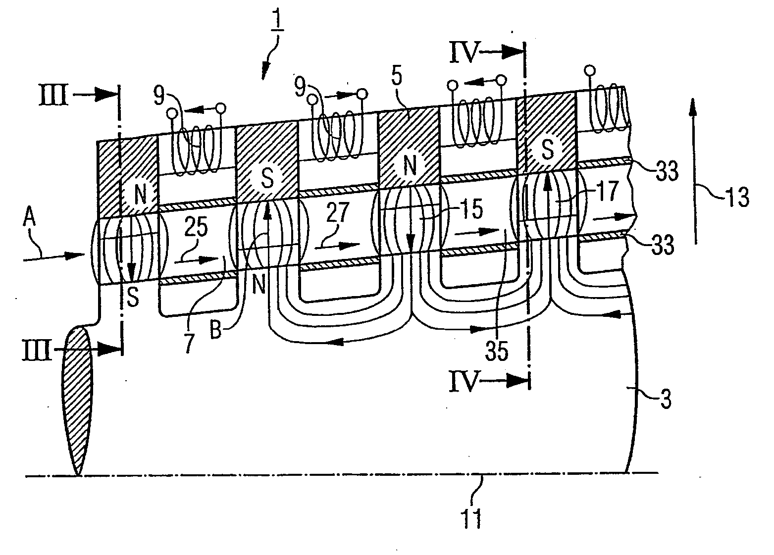
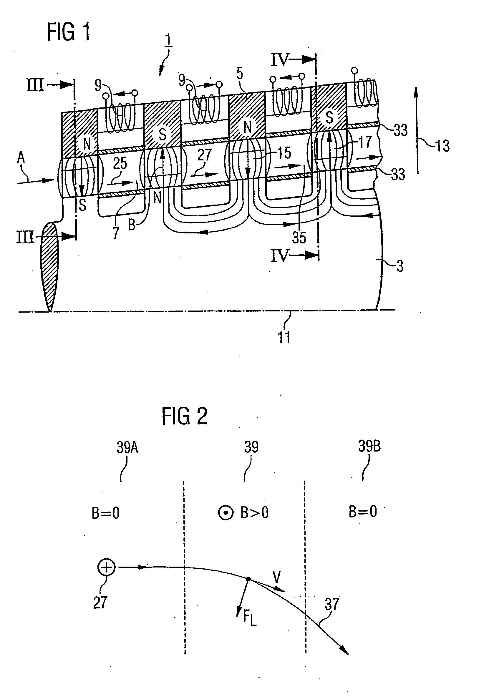
magnet, a both time-defined and spatially-defined magnetic field can be generated in the flow duct, thus leading to a defined deflection of charged particles in the action fluid and, on account of a pull effect as a result of pulse transfer, to a deflection of the action fluid itself. Deflection in this case takes place advantageously in the form of deflection planes between rotor and stator which are predetermined by the magnetic field and which possess a limited extent (localization of the magnetic field) in the main flow direction of the action fluid, for example in the axial direction in the case of an axial machine. The provision of a magnetic deflection plane for the charged particles or the action fluid by means of the magnetic field is very similar in its action to a conventional blade
cascade: where an axial turbomachine is concerned, for example, a deflection of a predominantly axial flow of the action fluid takes place in a flow with both an axial and a tangential component, this being because of the fact that, on account of the Lorenz force, a tangential component is imparted to the charged particles perpendicularly to the flow direction as a result of the interaction with the magnetic field. This deflection is associated with a conversion of pressure energy of the action fluid into
kinetic energy, in a similar way to a guide blade
cascade of a conventional
turbine. In the same way, it is possible, from a flow of the action fluid with an axial and tangential component, to achieve a conversion into a predominantly axial flow, with
kinetic energy being converted into mechanical work, in a similar way to a moving blade
cascade of a conventional
turbine. Consequently, in a similar way to conventional turbines, a suitable magnetic field configuration, with a magnetic field in the flow duct is generated spatially and, if appropriate, in time by means of the
magnet, makes it possible to have a progressive expansion of the action fluid, at the same time with the acquisition of mechanical work which can be transmitted in the form of
rotational energy to the rotor.
[0021] In a preferred embodiment of the turbomachine, the stator has the magnet. In this case, it is possible to integrate the magnet into the stator, so that the magnetic field generated by the magnet acts into the flow duct. In this case, it is also possible for the stator to have a plurality of magnets, so that the magnetic field can be set highly accurately in spatial terms in the flow duct according to the requirements. In the case of an axial machine, in which the stator conventionally at the same time forms an outer boundary of the flow duct and at the same time can function as an outer casing of the turbomachine, the magnet is advantageously particularly readily accessible for possible maintenance or inspection work or for the mounting of sensors (for example, magnetic field sensors) for the diagnostics of the turbomachine. Furthermore, if a ferromagnetic substance is selected, the stator material may at the same time be used for increasing the
magnetic flux density and consequently the magnetic field in the flow duct.
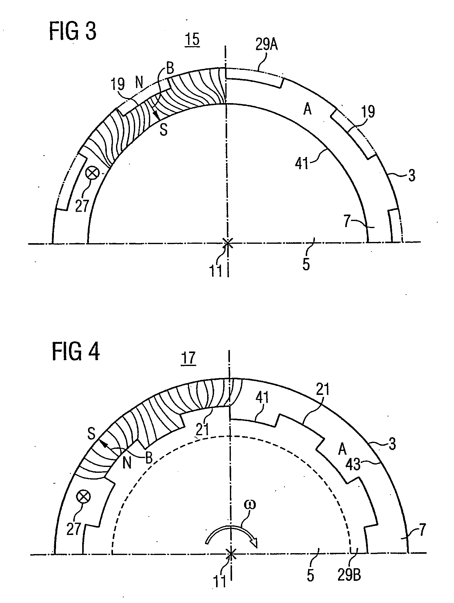
[0032] However, as compared with conventional blading, in the magnetic guide blade of the invention there is advantageously no need for any complex geometry for the projection. The projection may be configured, in terms of its geometry and its magnetic properties of the material, in such a way that the best possible results are achieved, in a similar way to a
pole piece. The projection may in this case be adapted in a constructively simple way to the radial symmetry, in particular to the cylinder-envelope-shaped
surface contour of the rotor, and consists of a material with high magnetic permeability, in order to achieve correspondingly high
magnetic flux densities of the radial deflection magnetic field.
[0036] The radially outwardly extending projection achieves a local increase in the
magnetic flux density, that is to say the magnetic
flux lines are concentrated in a space between the projection and the stator located opposite the projection in a radial direction. Owing to this configuration, approximately, a
magnetic dipole structure is implemented locally, in which case, depending on the selected polarity, magnetic
flux lines emerging, for example, from the projection form a magnetic
north pole, while the opposite stator surface which the magnetic
flux lines enter forms a south pole. The spatial confinement of the field allows an accurately directed deflection of charged particles in the action fluid, so that the moving blade based on the magnetic deflection of charged particles is thereby intimated, in a similar way to conventional turbomachines.
[0047] Also preferably, ions are formed by the
ionization of particles in the action fluid during the flow of the latter through the flow duct. The in-situ generation in this case has the
advantage that the ions can be generated in an accurately directed manner in the regions where they are also required for performing a magnetic deflection, that is to say in the magnetic guide blade region or the magnetic moving blade region.

