Electron gun

Inactive Publication Date: 2006-05-04
NETCOMSEC
View PDF4 Cites 10 Cited by
  • Summary
  • Abstract
  • Description
  • Claims
  • Application Information

AI Technical Summary

Benefits of technology

[0021] It is therefore an object of the present invention to provide an electron gun that allows fewer individual differences t

Problems solved by technology

A large variation in the perveance or between the cathode pellet and the Wehnelt electrode in the axial direction of electron emission results in problems such as the collision of electrons that are emitted from the cathode pellet with the anode electrode, or fluctuation of the electron beam diameter in the high-frequency circuit that causes a portion of the electron beam to hit the high-frequency circuit.
These problems bring about an increase in the power consumption or a reduction in the amplification performance of the microwave tube.
Problems were therefore encountered because high-precision jigs and tools were required to weld and secure the heater cap in order to keep the perveance and variation in the axial direction of electron emission of the cathode pellet and Wehnelt electrode within prescribed values,

Method used


Image

  • Electron gun
  • Electron gun
  • Electron gun

Examples


Embodiment Construction

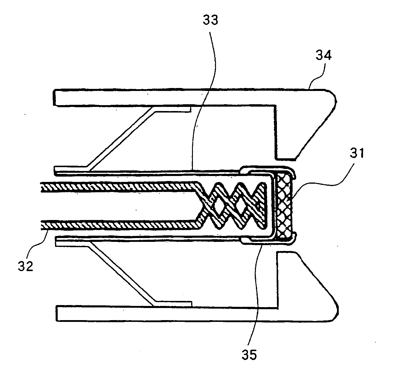
[0032]FIG. 3 is a sectional view showing an example of the configuration of an electron gun of the present invention.

[0033] As shown in FIG. 3, the electron gun of the present invention is a configuration in which cathode pellet 31 is formed in a disk shape and the periphery of cathode pellet 31 is engaged with and pressed against the sealed surface of heater cap 33 by means of retainer 35, whereby cathode pellet 31 is secured onto heater cap 33.

[0034] As with the prior art, cathode pellet 31 is secured at a position such that its electron emission surface and the surface of Wehnelt electrode 34 form approximately the same plane. Here, retainer 35 is a construction that protrudes by only its thickness with respect to the electron emission surface of cathode pellet 31. The construction is otherwise identical to an electron gun of the prior art and explanation of this construction is therefore here omitted.

[0035] In the electron gun of the present invention, the part of retainer 35...


PUM


Abstract

A disk-shaped cathode pellet is installed and secured by a retainer onto a heater cap that incorporates a heater. The part of this retainer that covers the periphery of the electron emission surface of the cathode pellet functions as a portion of a Wehnelt electrode. Alternatively, the retainer is formed such that the average angle of the surface with respect to the outermost shell of the electron beam matches the Pierce angle such that the part of this retainer that covers the periphery of the electron emission surface of the cathode pellet functions as a Wehnelt electrode.

Description

BACKGROUND OF THE INVENTION [0001] 1. Field of the Invention [0002] The present invention relates to an electron gun that is used in a microwave tube such as a traveling-wave tube or a klystron, and more particularly to a Pierce type electron gun that is provided with a Wehnelt electrode for focusing an electron beam. [0003] 2. Description of the Related Art [0004] Traveling-wave tubes and klystrons are electron tubes for amplifying high-frequency signals by means of the interaction between a high-frequency circuit and an electron beam that is emitted from an electron gun. Such electron tubes are constructions such as shown in FIG. 1 that include: electron gun 21 that emits electron beam 50; high-frequency circuit 22 for bringing about interaction between electron beam 50 that is emitted from electron gun 21 and high-frequency signals (microwaves); collector 23 for capturing electron beam 50 that is emitted from high-frequency circuit 22, and anode electrode 24 for guiding electron ...

Claims


Application Information

Patent Timeline
IPC IPC(8): H01J1/20
CPCH01J3/024H01J23/065H01J2225/14H01J23/06
Inventor MUNEHIRO, TAKATSUGUCHIBA, AKIRA
Owner NETCOMSEC
Why Eureka
Try Eureka