Method and apparatus for a chaotic computing module

a computing module and computing module technology, applied in the field of dynamic computing, can solve the problems of unable to change the functionality of hardware components such as logic gates once the component is fabricated, and the various hardware components of the computing system cannot be reconnected or reconfigured during operation

Active Publication Date: 2006-05-04
CDI2 LLC
View PDF10 Cites 12 Cited by
  • Summary
  • Abstract
  • Description
  • Claims
  • Application Information

AI Technical Summary

Problems solved by technology

Conventional computing systems also are static in nature and lack a flexible computing architecture.
Within static computing systems, the various hardware components of the computing system cannot be reconnected or reconfigured during operation.
For example, the functionality of hardware components such as logic gates cannot be changed once the component is fabricated.
In either case, the structure of the resulting circuit cannot be reconfigured or reordered into a different design.
Some computing modules, however, can be reconfigured to a limited degree.
For example, field programmable gate arrays provide a limited degree of flexibility with respect to reconfiguration.
In any case, while the present state of electronic design has begun to develop dynamic computing architectures, such efforts have been limited to simply redirecting signal flows or “rewiring” devices or components such as FPGA's.

Method used


Image

  • Method and apparatus for a chaotic computing module
  • Method and apparatus for a chaotic computing module
  • Method and apparatus for a chaotic computing module

Examples


Embodiment Construction

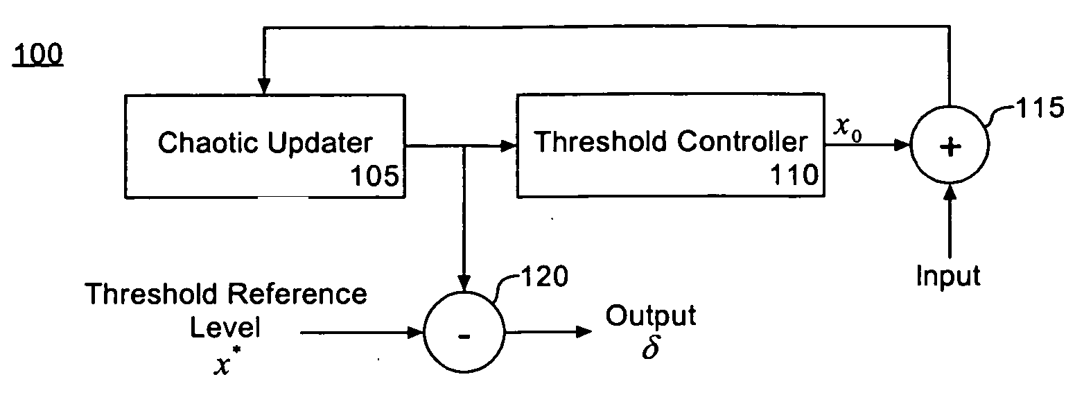
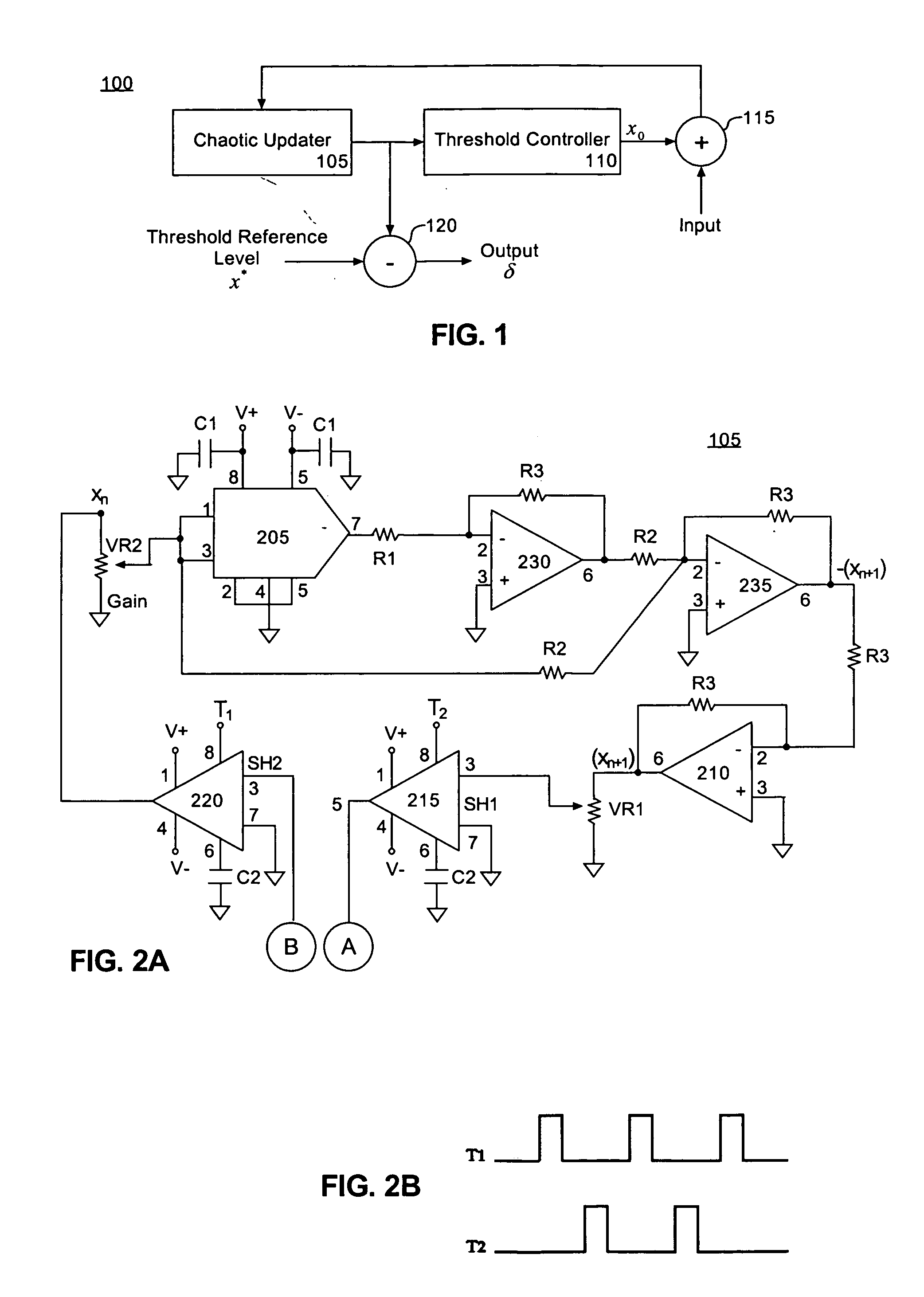
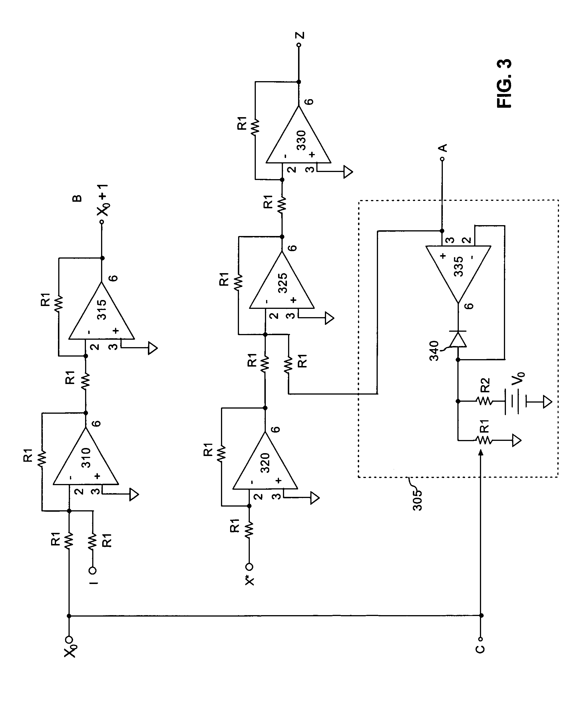
[0024] The present invention provides a chaotic logic gate method, system, and apparatus that can be configured to function as any of a variety of different logic gates such as an “and” (AND) gate, an “or” (OR) gate, an “exclusive or” (XOR) gate, and a “not” (NOT) gate. The functionality of the chaotic logic gate can be altered by changing one or more reference voltages provided to the gate. Accordingly, a chaotic logic gate in accordance with the inventive arrangements disclosed herein, for example, can function as one type of gate, such as an AND logic gate, and during operation be instructed to begin operating or functioning as another type of logic gate, such as an OR logic gate.

[0025] Table 1 below illustrates a truth table of basic operations. For example, column 3 illustrates the function of an AND gate given inputs (I1,I2), column 4 shows the function of an OR gate given inputs (I1, I2), and column 5 shows the function of an XOR gate given inputs (I1,I2). The second portion...


PUM


Abstract

A logic gate array for implementing logical expressions is provided. The array includes a dynamically configurable logic gate having a chaotic updater for causing the logic gate to alternately operate as one of a several different logic gate types, the dynamically configurable logic gate alternating from operating as one logic gate type to a different logic gate type in response to one or more reference signals. The array also includes one or more additional logic gates.

Description

CROSS REFERENCE TO RELATED APPLICATIONS [0001] This application is a continuation of and, accordingly, claims the benefit of U.S. patent application Ser. No. 10 / 680,271, filed in the U.S. Patent and Trademark Office on Oct. 7, 2003, and issued as U.S. Pat. No. ______ on ______.BACKGROUND OF THE INVENTION [0002] 1. Technical Field [0003] This invention relates to the field of dynamic computing and, more particularly, to a chaotic computing architecture for logic gates. [0004] 2. Description of the Related Art [0005] Conventional computing systems rely upon timed operations and Boolean algebra to perform calculations. That is, the flow and processing of signals within conventional computing systems is under the control and coordination of a timing source such as a signal from a system clock. With the passing of each clock cycle, signals can be processed, typically using various combinations of logic gates to implement one or more Boolean algebraic functions. [0006] Conventional comput...

Claims


Application Information

Patent Timeline
Patent Type & Authority Applications(United States)
IPC IPC(8): H01L25/00G06F17/50H03K19/177G06FG06F7/38G06G7/00G06G7/38G06N7/08H03K17/693H03K19/173
CPCG06N7/08
Inventor DITTO, WILLIAM L.MURALI, KRISHNAMURTHYSINHA, SUDESHNA
Owner CDI2 LLC
Why Eureka
Try Eureka