Computer-aided-design of skeletal implants

a computer-aided design and implant technology, applied in the field of cranial implants, can solve the problems of difficult computer-aided design of patient-specific implants, and their production prior to surgery, and achieve the effect of maintaining surface curvature continuity

Inactive Publication Date: 2006-05-04
OSTEOPLASTICS
View PDF2 Cites 584 Cited by
  • Summary
  • Abstract
  • Description
  • Claims
  • Application Information

AI Technical Summary

Benefits of technology

[0030] Still further according to the present invention, the steps include redistributing the color values in an image referred to as a histogram over the entire intensity scale so as to make the contrast between low an high curvature regions visually useful.
[0032] Also according to the present invention, the steps include resampling the defect-filling template surface to have uniformly shaped and spaced triangles; the use of these resampled manifolds for the accurate partitioning of a defect filling template image; and articulating the prototype implant surface while maintaining surface curvature continuity across the defect margin. The method also includes the step of using an implant surface smoothing algorithm that removes slice edge artifact when volume image slices have larger inter-slice than pixel dimensions.

Problems solved by technology

The design of patient-specific implants, and their production prior to surgery, is a difficult task with traditional computer aided design (CAD) tools.

Method used


Image

  • Computer-aided-design of skeletal implants
  • Computer-aided-design of skeletal implants
  • Computer-aided-design of skeletal implants

Examples


case 1

eral Cranial Defect

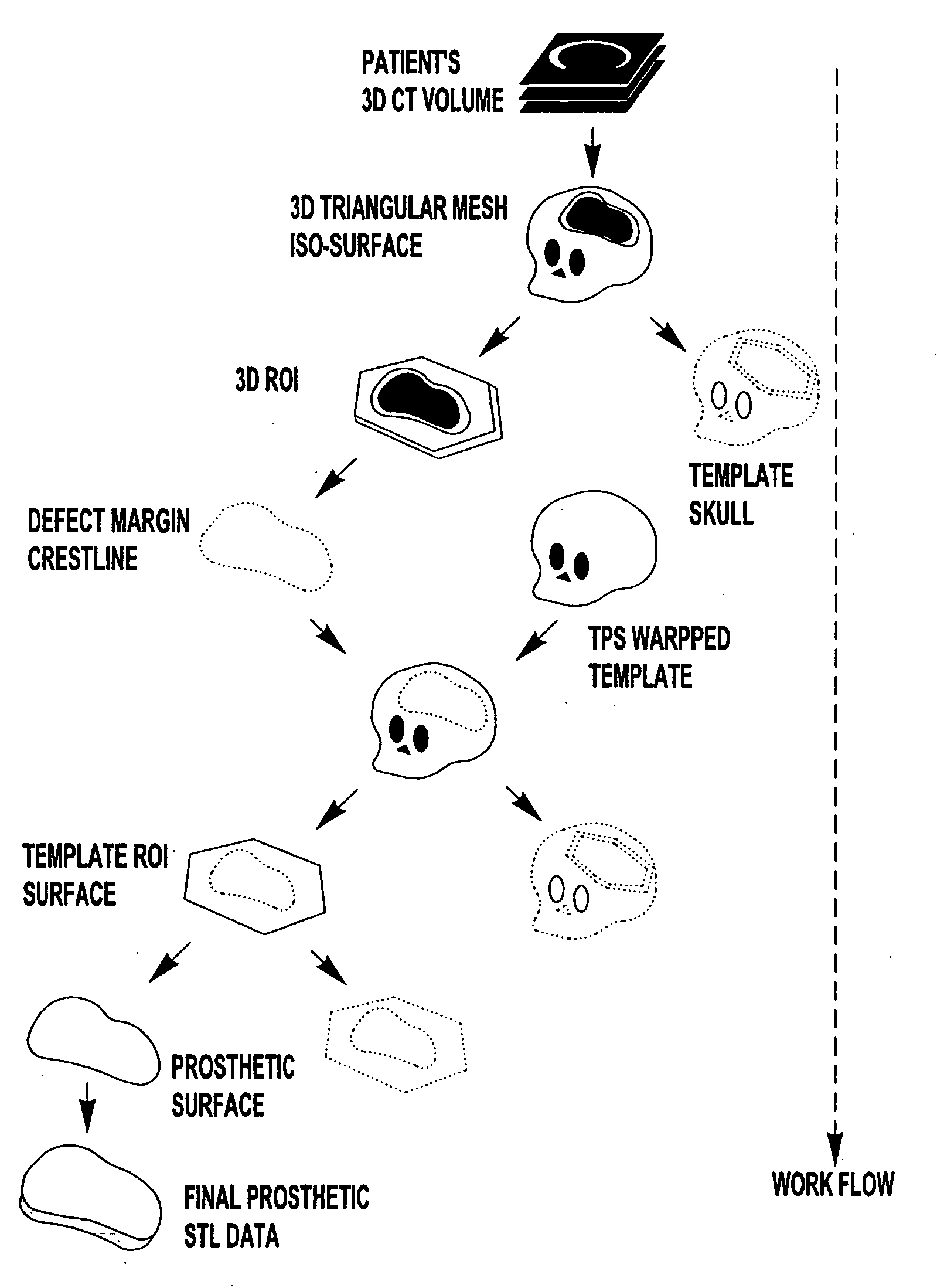
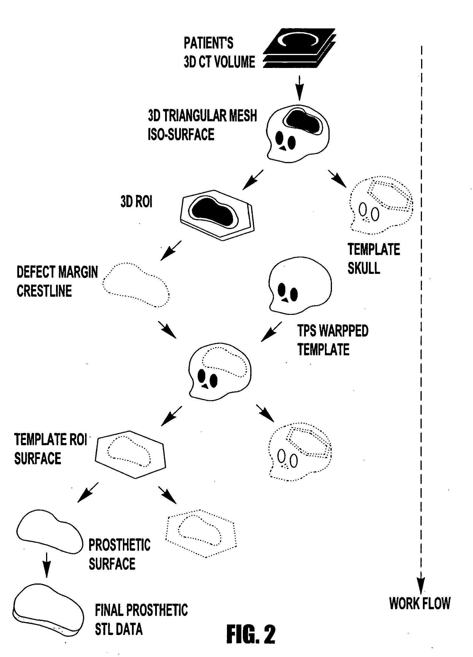
[0205] In a case where the defect is located unilaterally, the left-right mirror image of the patient's original skull isosurface image is left to become the skull template surface. For appropriate left-right mirroring, the patient needs to lie in a supine (i.e., on their back) position during the CT scanning process. This pose allows for all axial slices to be close to perpendicular of the patient's right-left plane. This will avoid top-to-bottom or front-to-back mirroring. Following appropriate left-right mirroring, geometric translation of the centroid of the left-right mirrored skull template to the original cranial isosurface centroid results in a rough match since the scaling factors are identical.

[0206] The displacement is due to the patient not lying in a fully supine position, tilting of other axes that are parallel to the patient's head, and non-ideal symmetry of the human cranium. These parameters are rarely adjusted during the CT-scanning phase, causi...

case 2

Spanning the Center of the Cranium

[0208] Cranial defects spanning both sides of the skull leave too little anatomy to provide sufficient biological homology in a left-right mirrored image. In these cases, an average skull template surface is used. Unlike a mirrored template surface, the average skull image must be scaled to an appropriate size and reoriented for the patient's reference frame. For this reason, the Procrustes superimposition method is used to match the skull template so that the two differently sized cranial images can be initially aligned. Because the Procrustes superimposition method also requires two sets of biologically homologous landmark configurations, an operator must manually prepare them as well. As with the case for a left-right mirrored template, the resized average template surface is then deformed via TPS warp to provide a useful registration.

Skull Template Registration Tools

[0209] In order to deform the cranial template surface to the patient's skull...

verification and modification

Implant Taper Verification and Modification

[0298] The taper should accurately contact the cranial defect, but should not penetrate surrounding boney structures. We evaluate the amount of taper contact with the patient's polygonal mesh isosurface image is before producing the final implant shape. Once again the RAPID collision detection algorithm is employed to numerically and visually determine the degree of intersection between the tapered edge surface and the defect site. For computational efficiency, the 3D ROI that includes the cranial defect site acquired from the full skull image prior to the cranial defect margin crestline identification step above is reused.

[0299] Although the RAPID algorithm is capable of detecting collisions occurring between pairs of triangles. FIG. 29 depicts intersecting regions between the potential implant taper and the cranial defect site as detected by the RAPID algorithm. The shaded region represents the bony tissue structure of the cranial defect...


PUM


Abstract

The present invention is directed to a computer aided design method for producing an implant for a patient prior to operation comprising the steps of: generating data with a non-invasive 3D (3-dimensional) scan of the patient's defect site that digitally represents the area that will receive the implant; designing and validating an implant on a computer based on digital data generated from a volume image of the patient; and fabricating the implant based solely on the implant design data generated on computer.

Description

CROSS-REFERENCE TO RELATED APPLICATIONS [0001] This application claims the benefit of U.S. Provisional Patent Application No. 60 / 477,694 filed on Jun. 11, 2003 which is incorporated herein by reference. [0002] This application is a continuation of copending PCT Patent Application No. PCT / US2004 / 018807 filed on Jun. 14, 2004, which is incorporated herein by reference.TECHNICAL FIELD [0003] The present invention generally relates to the generation of patient-specific, pre-operatively fabricated prosthetic implants and more particularly to a cranial implant. BACKGROUND OF THE INVENTION [0004] Large (>100cm2) cranial defects require well-fitting prosthetic implants to protect the patient's brain from trauma or infection, and to restore an aesthetic shape to the patient's head. During the cranial reconstructive surgery referred to as cranioplasty, if sufficient cranial bone is not available for engraftment, then malleable and biocompatible materials are used to fashion an implant. The...

Claims


Application Information

Patent Timeline
Patent Type & Authority Applications(United States)
IPC IPC(8): A61B5/05A61FA61F2/28A61F2/30G06F19/00G06T17/10
CPCA61F2/2875A61F2/30942A61F2002/30943A61F2002/30952G05B2219/45168G06F19/3437G06T17/10Y10S623/901G16H50/50B33Y80/00B33Y50/00
Inventor DEAN, DAVIDMIN, KYOUNG-JUNERATCHESON, ROBERT A.
Owner OSTEOPLASTICS
Why Eureka
Try Eureka