Flush toilet unit

a technology for flushing toilets and toilets, applied in the field of flushing toilets, can solve the problems of insufficient operational reliability, urine-volume measurement systems, and various problems, and achieve the effect of improving urine-volume measurement accuracy

Inactive Publication Date: 2006-05-11
TOTO LTD
View PDF5 Cites 46 Cited by
  • Summary
  • Abstract
  • Description
  • Claims
  • Application Information

AI Technical Summary

Benefits of technology

[0011] In view of the above problems, it is an object of the present invention to provide a flush toilet unit capable of easily learning a volume of voided urine and an index related to the urine volume with high reliability simply by urinating in a lavatory in a usual manner.
[0095] In the flush toilet unit having this feature, the pressure of the constant-pressure means maintained at a constant value is applied to the pressure sensor to calibrate the pressure sensor. This makes it possible to provide enhanced urine-volume measurement accuracy.

Problems solved by technology

As described above, the previously proposed systems for measuring a urine volume or a urine flow rate involve various problems.
Moreover, the aforementioned conventional urine-volume measuring systems have a problem about insufficient operational reliability due to properties of urine as a measurement target.
That is, urine containing a large amount of electrolyte, such as sodium chloride, is liable to corrode measuring-elements / devices made of metal and consequently cause a negative effect on functions of the measuring-elements / devices.
Further, the flush toilet disclosed in the Japanese Patent Laid-Open Publication No. 08-299348 has a problem about poor user-friendliness, because it is required to take a long time for preparation of a urine-volume measuring operation, and a user is obliged to hold his / her urine until initiation of the measurement.

Method used


Image

  • Flush toilet unit
  • Flush toilet unit
  • Flush toilet unit

Examples


first embodiment

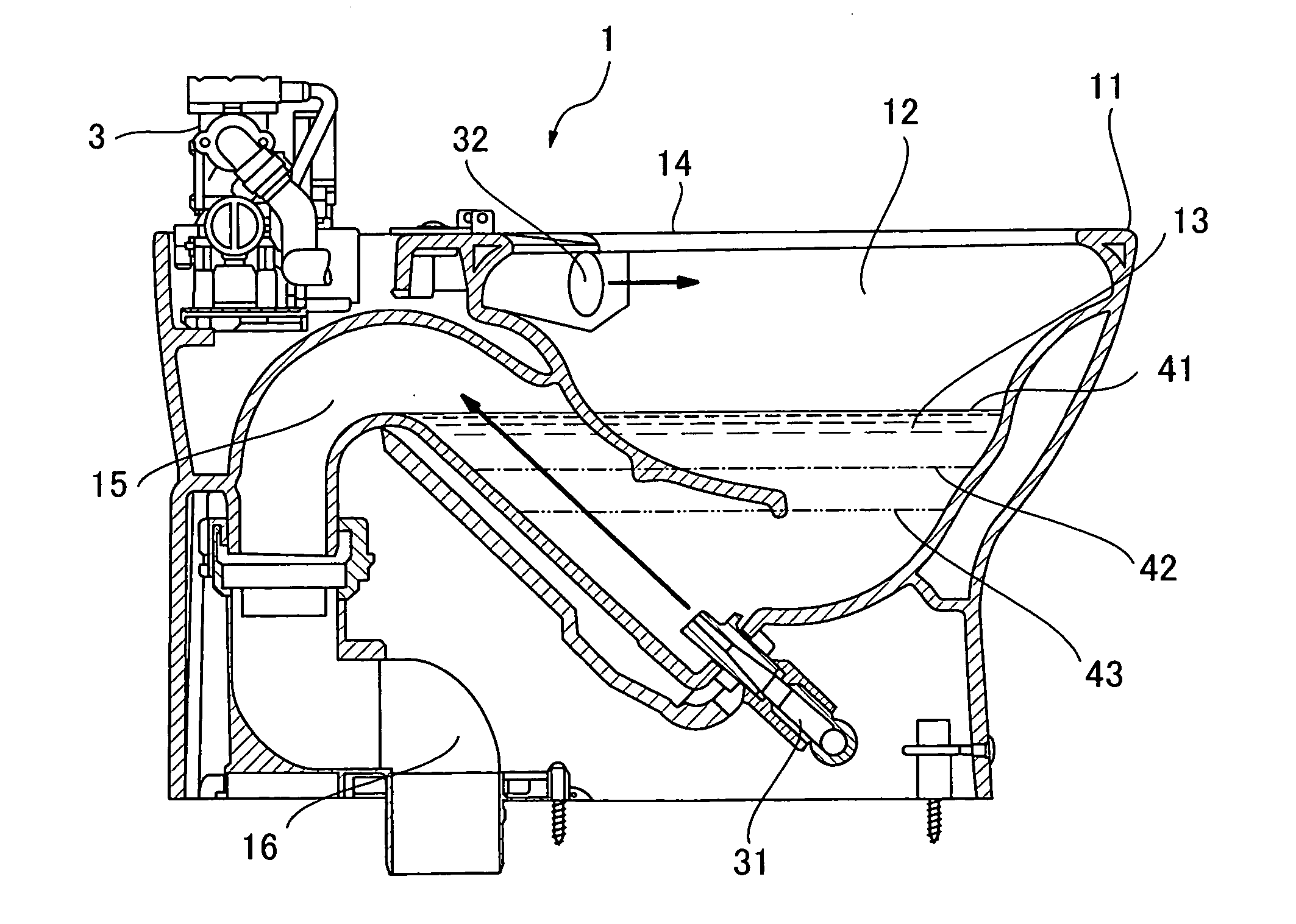
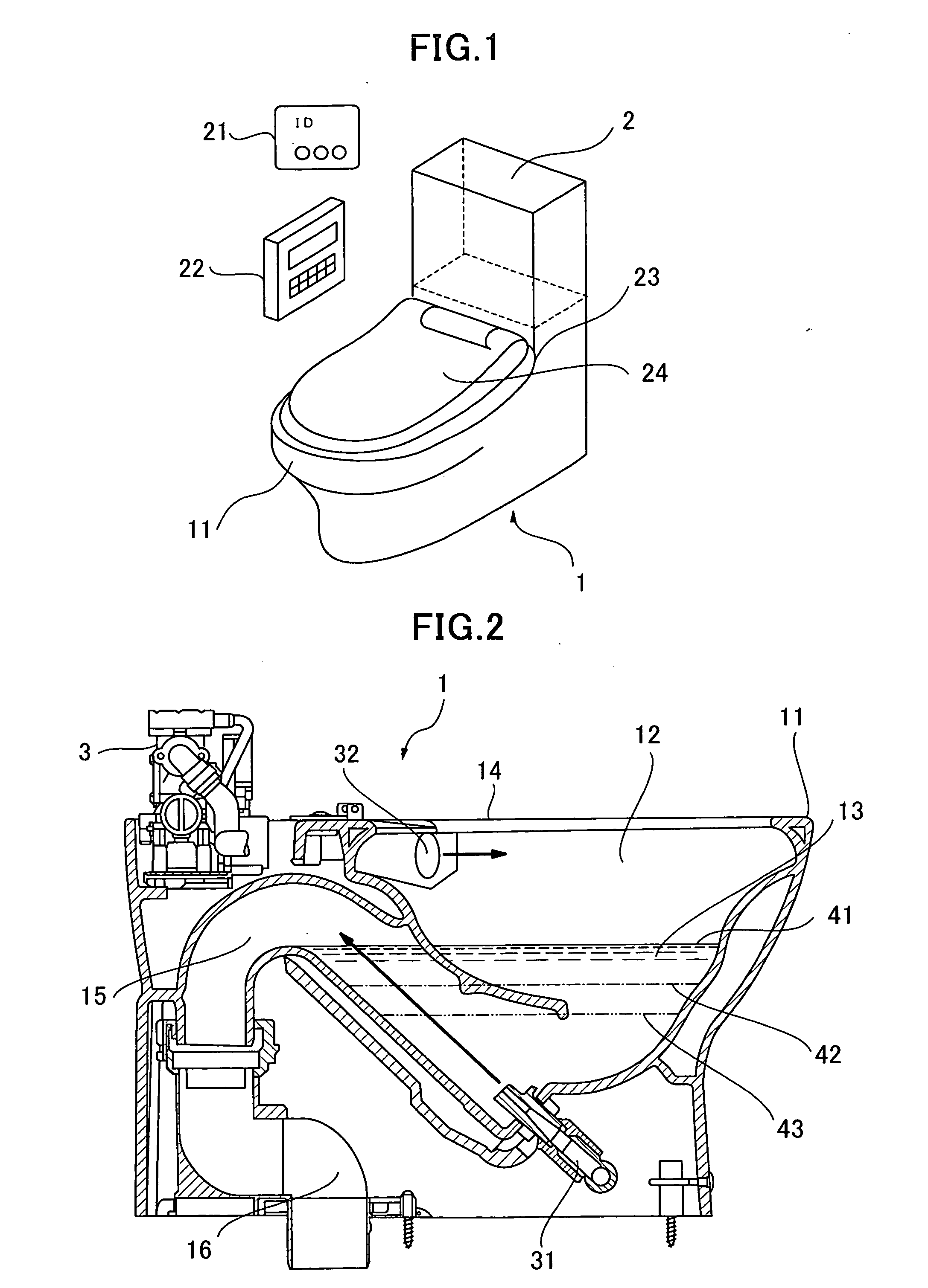
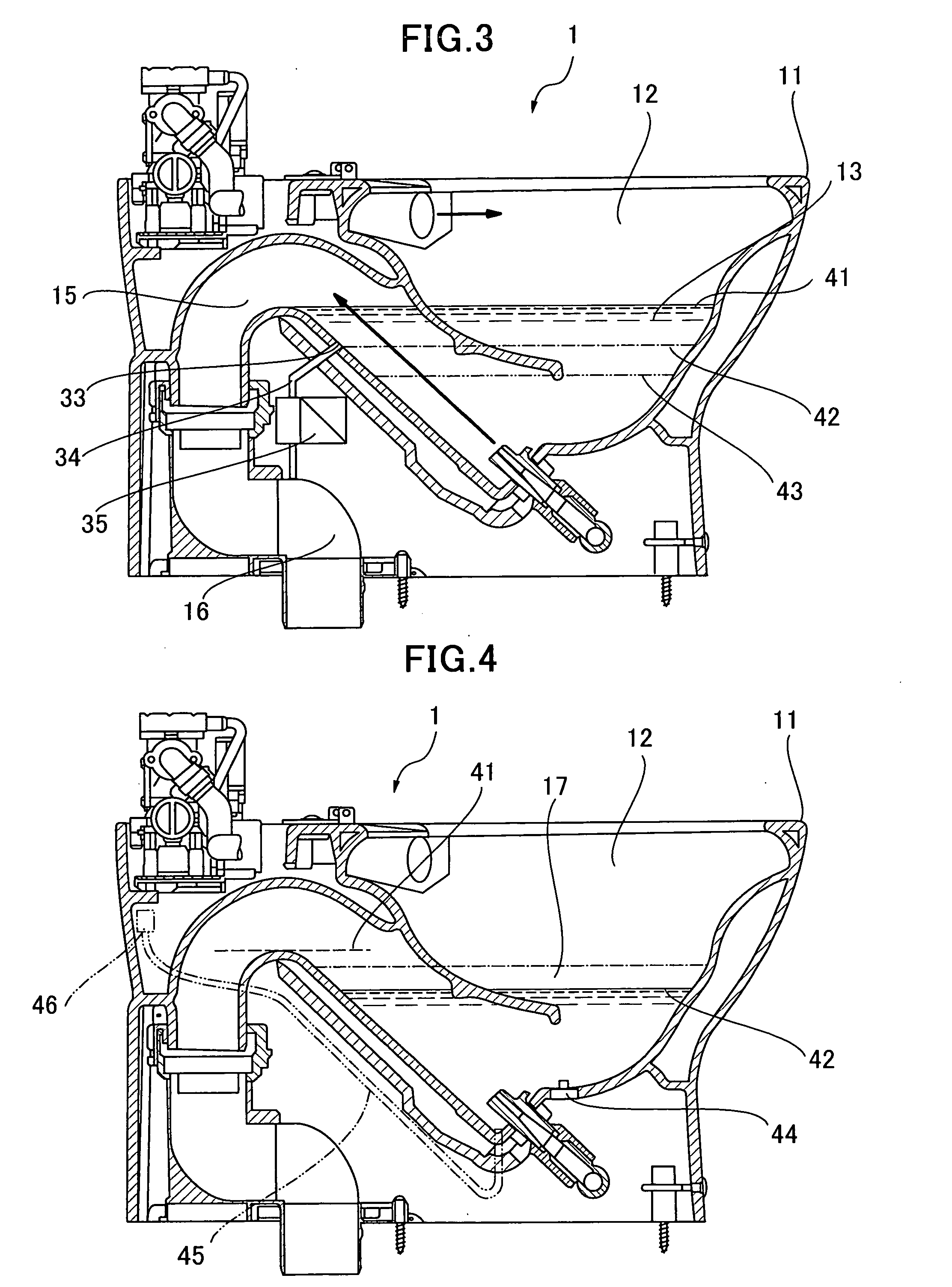
[0144]FIG. 1 is a perspective view showing a flush toilet unit according to the present invention.

[0145] The flush toilet unit 1 comprises a western-style flush toilet 11 for receiving therein excretions of a user and discharging the excretions to a sewer system, and a functional case 2 incorporating various functions including urine-volume estimation means. The flush toilet 11 and the functional case 2 are integrated into one unit. The water closer unit 1 further comprises a flush toilet seat 23 having a top surface for allowing a user to sit thereon, and a flush toilet seat cover 24 rotatably attached to the flush toilet 11 and adapted to cover the seat 23. The flush toilet unit 1 has an associated device including an ID card 21 for identifying a user, and a manual operation / display section 22. The flush toilet unit 1 is designed to be activated so as to place various functions thereof in a standby state, in response to readout or scanning of personal authentication information st...

second embodiment

[0188] A flush toilet unit according to the present invention will be described below.

[0189]FIG. 18 is a perspective view showing a flush toilet unit with urine-volume measuring functions according to the second embodiment of the present invention.

[0190] The flush toilet unit 201 comprises: a western-style flush toilet 211 including a flush toilet seat 221 and a flush toilet cover 222; and a functional case 202 rotatably supporting the flush toilet seat 221 and the flush toilet cover 222. If a space of the functional case 202 is not sufficient to house all associated devices, it may further include a device cabinet 205 adapted to house a part of the devices and integrally connected to the closet unit 201 through a back surface thereof and piping members. A bowl 212 is formed inside the western-style flush toilet 211 to pool a certain volume of pooled water 213 for receiving excretions of a user. The bowl 12 has a top end formed as a rim surface 214 adapted to come into contact with...

third embodiment

[0219] A flush toilet unit according to the present invention will be described below.

[0220]FIG. 24 is a perspective view generally showing the flush toilet unit according to the third embodiment of the present invention, and FIG. 25 is a sectional side view of the flush toilet unit.

[0221] The flush toilet unit 401 comprises a western-style flush toilet 402, and a cabinet 404 housing various functional sections or elements / devices for operating the flush toilet unit 401.

[0222] The western-style flush toilet 402 includes a bowl 406 for receiving excretions, such as urine and feces, voided by a user, etc., a rim water-spouting nozzle 407 for spouting water from a rim portion of the bowl 406, and a trap portion 408 fluidically connected to a bottom portion of the bowl 406 and adapted to form a water seal for the bowl 406. The western-style flush toilet 402 further includes a water jet nozzle 409 attached to the bottom portion of the bowl 406 and adapted to inject flushing water towar...


PUM


Abstract

Disclosed is a flush toilet unit, which is capable of measuring a urine volume with a high degree of accuracy without making a significant change to a conventional water-closet structure. The flush toilet unit (1) of the present invention comprises a bowl (12) for receiving urine of a user therein, a trap portion (15) fluidically connected to the bowl and adapted to guide a pooled water in the bowl to a sewer pipe and to form a water seal relative to the sewer pipe, pooled-water discharge means (34, 35) for lowering a pooled-water level in the bowl to a given water level which is below an overflow water level in the trap portion, water-level measurement means (46) for measuring a water-level variation between the lowered pooled-water level set by the pooled-water discharge means and a water level in the bowl after urination by the user, urine-volume calculation means for calculating a volume of urine voided into the bowl by the user, in accordance with the water-level variation value measured by the water-level measurement means, and water supply means for supplying water into the bowl to return the pooled-water level in the bowl to the overflow water level.

Description

TECHNICAL FIELD [0001] The present invention relates to a flush toilet unit, and more particularly to a flush toilet unit capable of measuring a volume of voided urine and / or biological information related to the urine volume. BACKGROUND ART [0002] Biological information to be obtained from urine is valuable in the medical fields, particularly in the fields of preventive medical care and therapeutic management. While a urine sample has heretofore been collected using a collecting vessel, such as a urine collection cup, this conventional technique lacks consideration to comfort for patients required for offering their urine samples. Thus, there is the need for providing a technique for allowing a volume of voided urine and / or biological information related to the urine volume to be measured through urination at a lavatory in a usual manner. Further, there is the need for providing a flush toilet unit suitable for measuring an index necessary not only for preventive medical care, but ...

Claims


Application Information

Patent Timeline
Patent Type & Authority Applications(United States)
IPC IPC(8): E03D11/00A61B10/00E03D9/05E03D11/08G01F23/00
CPCA61B10/007E03D9/05E03D11/08E03D2201/30G01F23/00
Inventor YAMASAKI, HIRONORIINMA, YASUSHIKANEKUNI, NOBUHIKO
Owner TOTO LTD
Why Eureka
Try Eureka