Positioning system and method of orienting an object using same

Inactive Publication Date: 2006-05-11
UNIRAC INC
View PDF7 Cites 54 Cited by
  • Summary
  • Abstract
  • Description
  • Claims
  • Application Information

AI Technical Summary

Benefits of technology

[0010] Accordingly, it is an advantage of the present invention that a system is provided for orienting an object relative to a base.
[0011] It is another advantage of the present invention that a system is provided that orients a heavy or large object with a high degree of precision.
[0012] Another advantage of the present invention is that a system is provided for orienting an object that experiences a highly variable load

Problems solved by technology

Unfortunately, the highly precise tracking and control systems that are desirable for use with smaller objects are prohibitively expensive for larger systems.
Moreover, some prior art positioning systems for large objects, such as solar collectors, suffer from positional uncertainty (e.g., approximately 0.5° to 2°).
The bearings and other linkages can introduce some degree of backlash and non-linearity that detract from the precision of the positional movements.
In addition, loads can deflect and deform the drive mechanism also detracting from the precision of the position movements, unless the system is stiff.
Large systems favor hydraulic drive mechanisms over electrical drive mechanisms for reasons of cost and strength.
However, another factor that contributes to positional uncertainty in hydraulic systems is attributed to the compressibility of the oil used for the hydraulic systems.
Further uncertainty may res

Method used


Image

  • Positioning system and method of orienting an object using same
  • Positioning system and method of orienting an object using same
  • Positioning system and method of orienting an object using same

Examples


Example

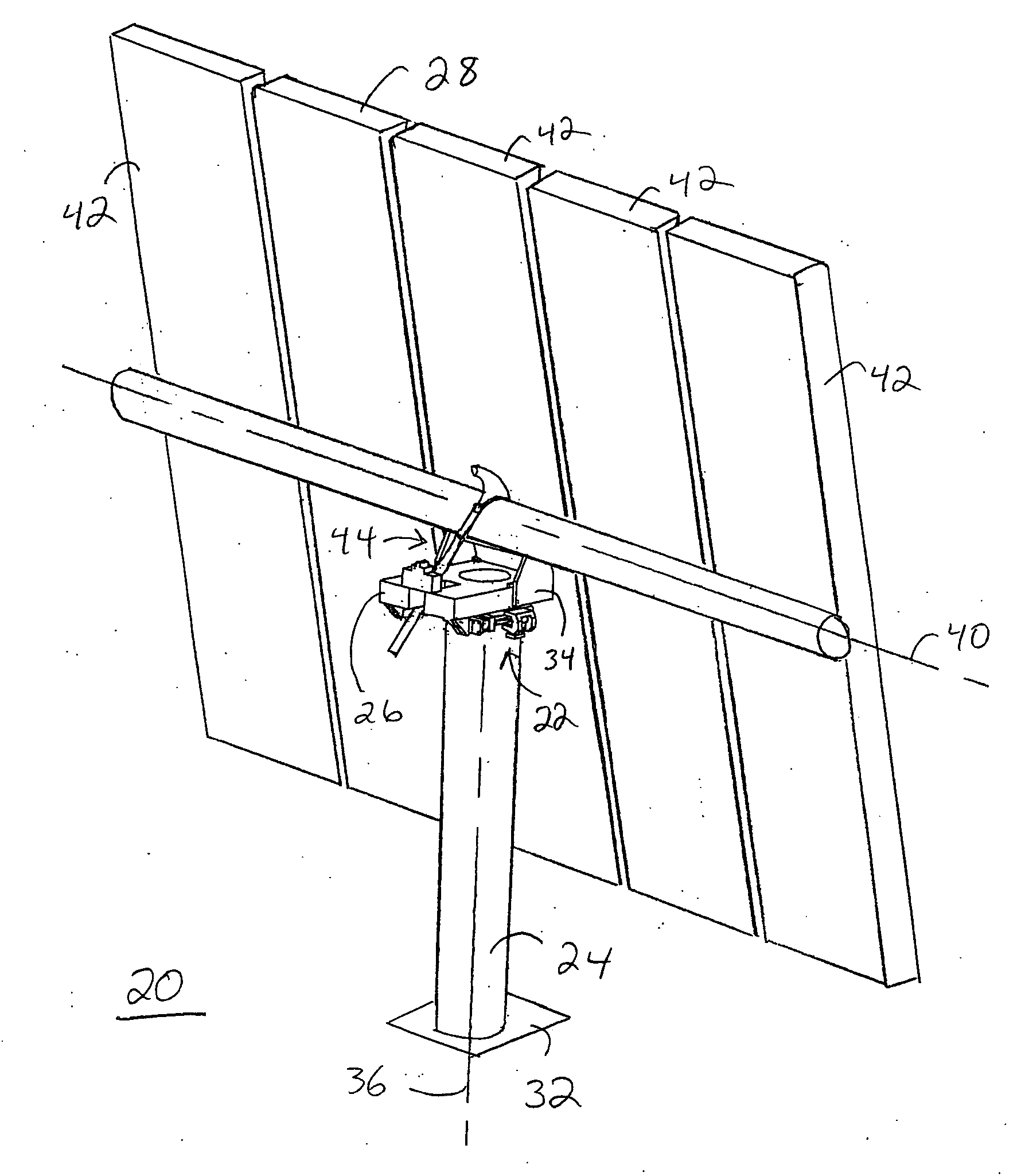
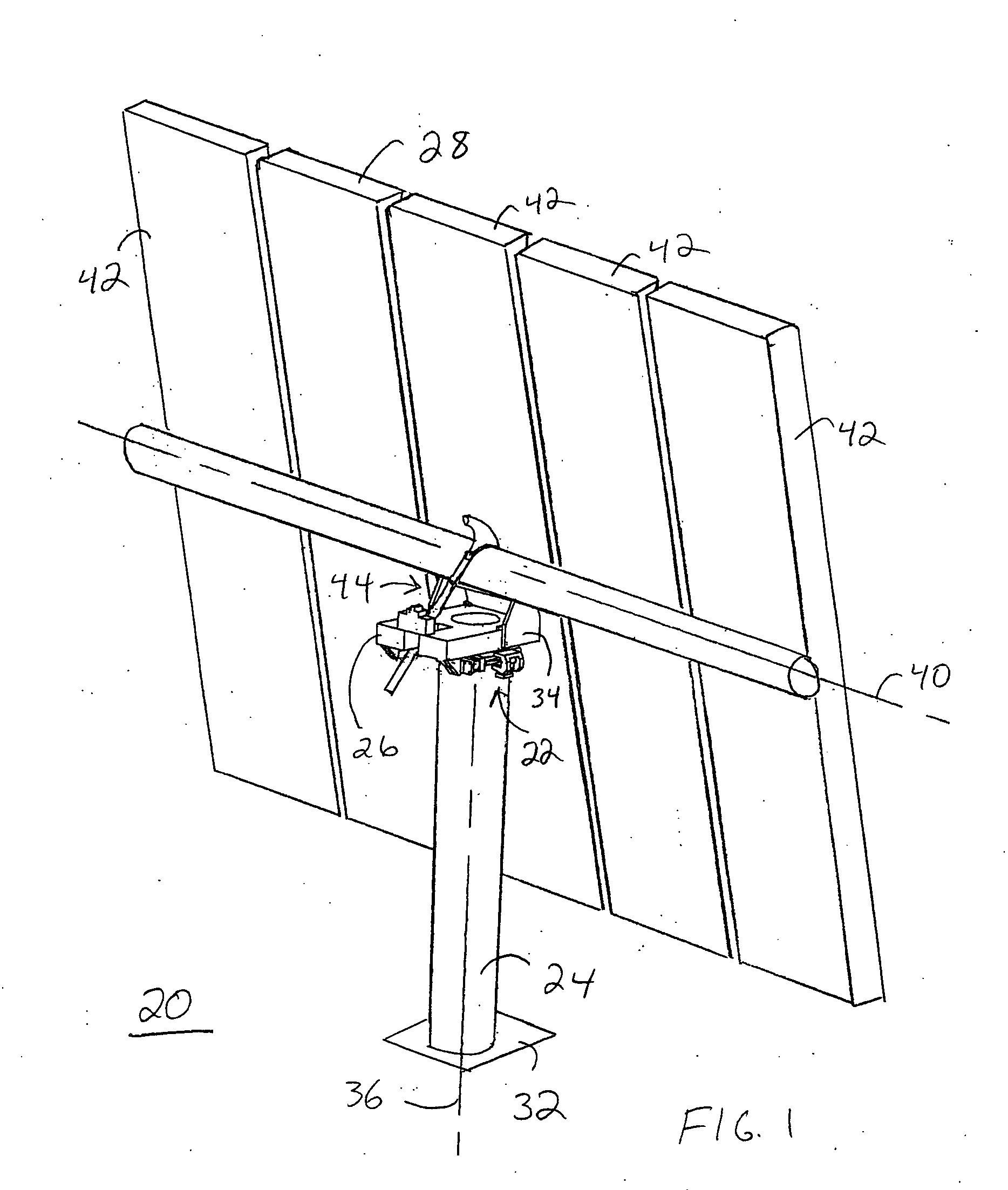
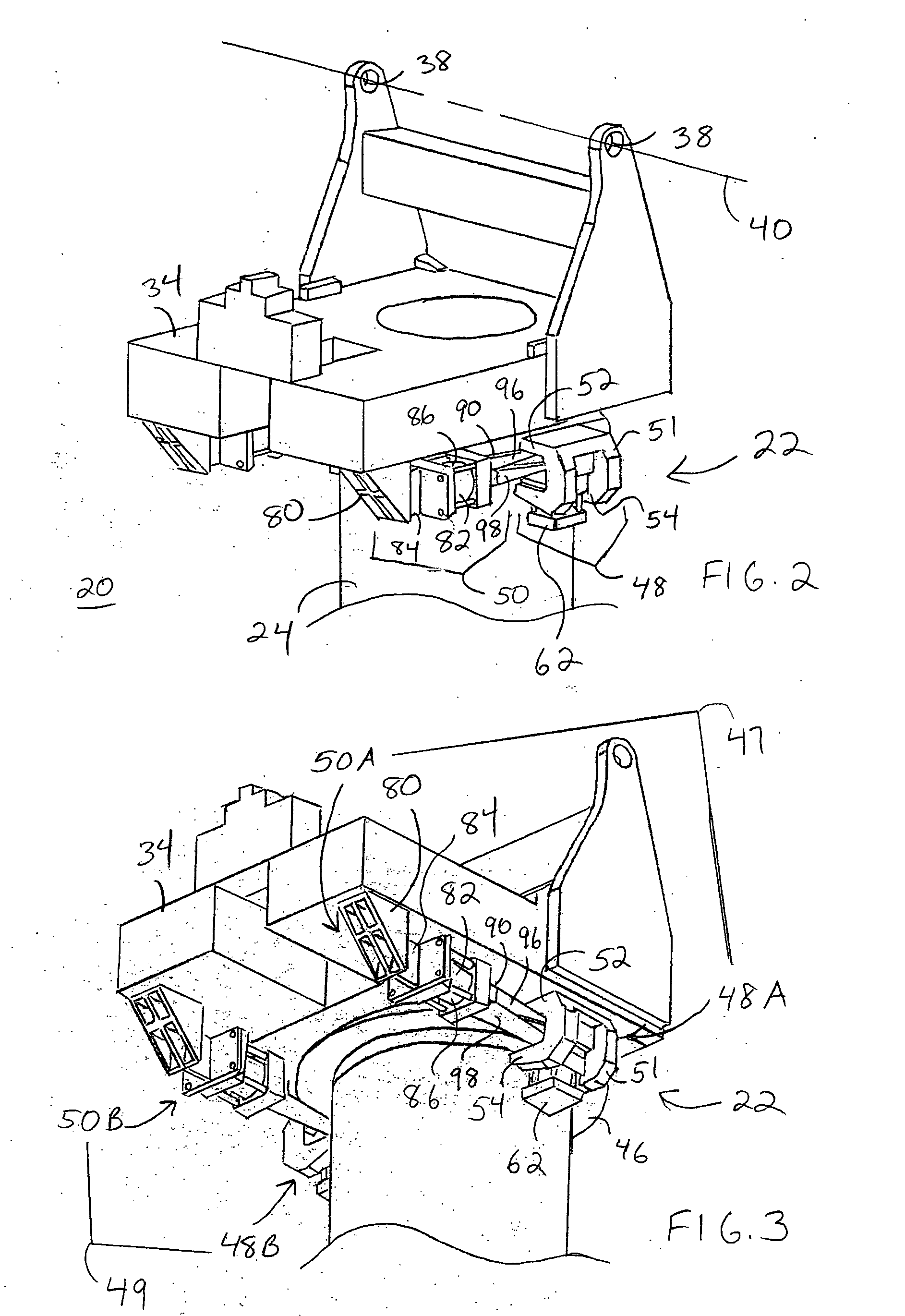
[0030] The present invention includes a positioning system and methodology for utilizing the positioning system to precisely orient an object relative to a base to which the object is rotatably coupled. In a preferred embodiment, the positioning system orients the object in azimuth. The object may be a device that is intended to face a given target in the celestial hemisphere during normal operations. Such devices include, but are not limited to, telescopes, radar systems, directional antennas, solar collectors, and other devices that track from above. Moreover, the object may be a large object, such as a crane. The term “large” refers to an object having a surface that exhibits an area of at least one hundred square meters. The term “large” can also refer to a heavy object, or an object subjected to heavy or variable loads, that may or may not have an area of at least one hundred square meters.

[0031] For clarity of illustration, the positioning device and methodology will be descr...


PUM


Abstract

A system (22) for orienting an object (28) relative to a base (24) to which the object (28) is rotatably coupled includes a braking surface (46) in fixed relation with the base (24). A brake (48) is engaged with the braking surface (46). A linear actuator (82) has a body (86) in fixed attachment with the object (28) via a strap member (84) and a coupling element (80). The linear actuator (82) also includes a rod (88) in fixed communication with the brake (48) through an elongate member (90) that flexes in response to a braking force (66) imposed on the braking surface (46) by the brake (48). The linear actuator is activated to generate linear motion (120) of the rod (88). The linear motion (120) of the rod (88) causes rotational motion (122) of the object (28). The strap member (84) is enabled to flex as the object (28) rotates.

Description

TECHNICAL FIELD OF THE INVENTION [0001] The present invention relates to the field of positioning systems. More specifically, the present invention relates to a system for precise orientation of an object about an axis. BACKGROUND OF THE INVENTION [0002] Celestial tracking apparatuses are devices that track or face a given object in the celestial hemisphere during normal operations. Such apparatuses are typically configured for use as telescopes, radio telescopes, radar systems, directional antennas, solar collectors, solar dishes, and so forth. [0003] Such tracking systems typically employ two independent systems to tilt the object, i.e., the telescope, radar dish, antenna, collector, and so forth, about two axes. IN one arrangement, one axis is horizontal, commonly called “elevation”. The elevation axis is the axis about which the object may be tilted within an angular range of about ninety degrees, from the horizon to looking straight up. The other axis is vertical, commonly call...

Claims


Application Information

Patent Timeline
IPC IPC(8): F24J2/52F24S50/20
CPCF24J2/38F24J2/523F24J2/542F24J2002/5441F24J2002/5458Y10T74/1488H01Q1/125H01Q3/08Y02E10/47Y10T74/1453F24J2002/5496F24S25/10F24S30/452F24S50/20F24S2030/115F24S2030/133F24S2030/19
Inventor HAYDEN, HERBERT T.
Owner UNIRAC INC
Why Eureka
Try Eureka