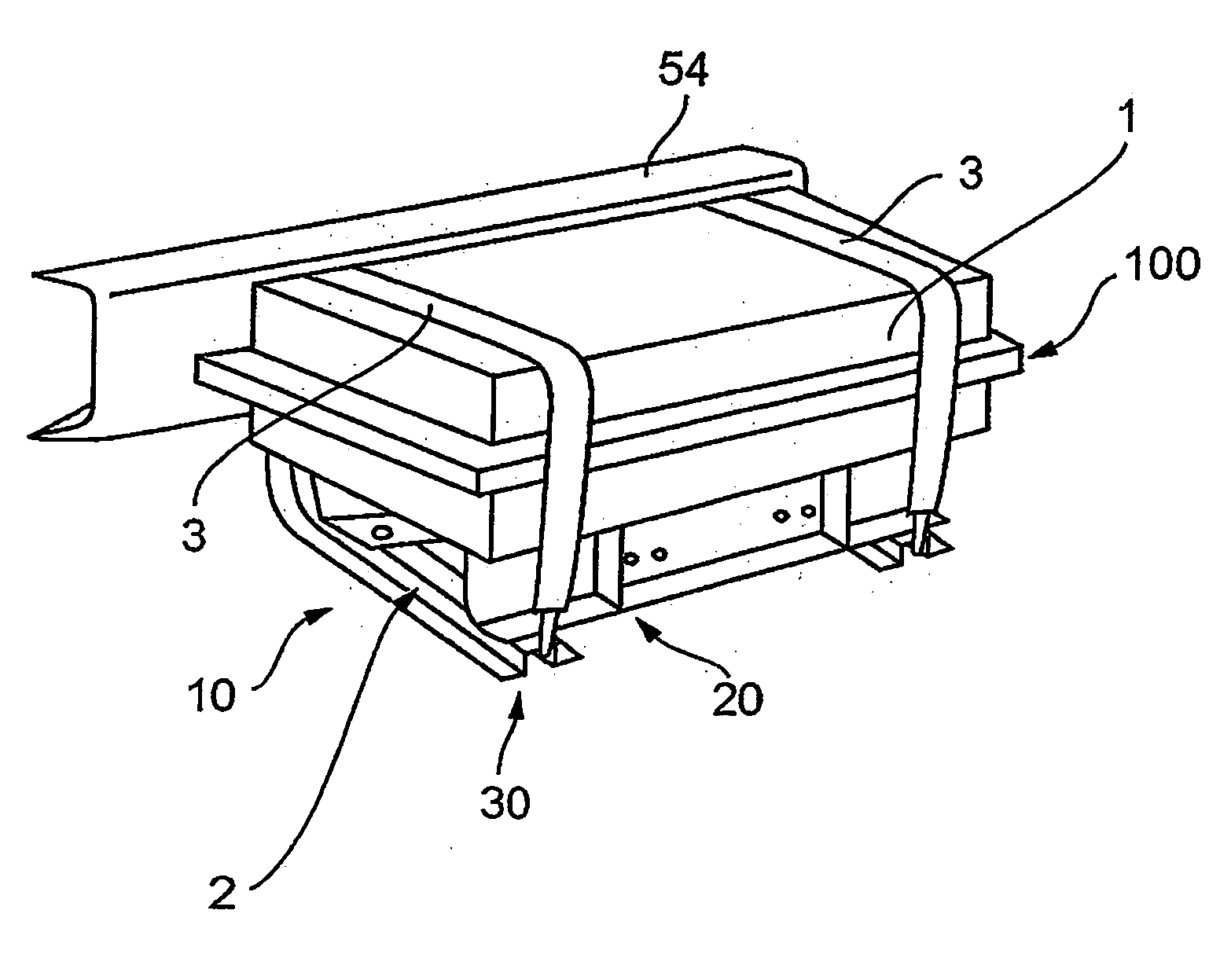
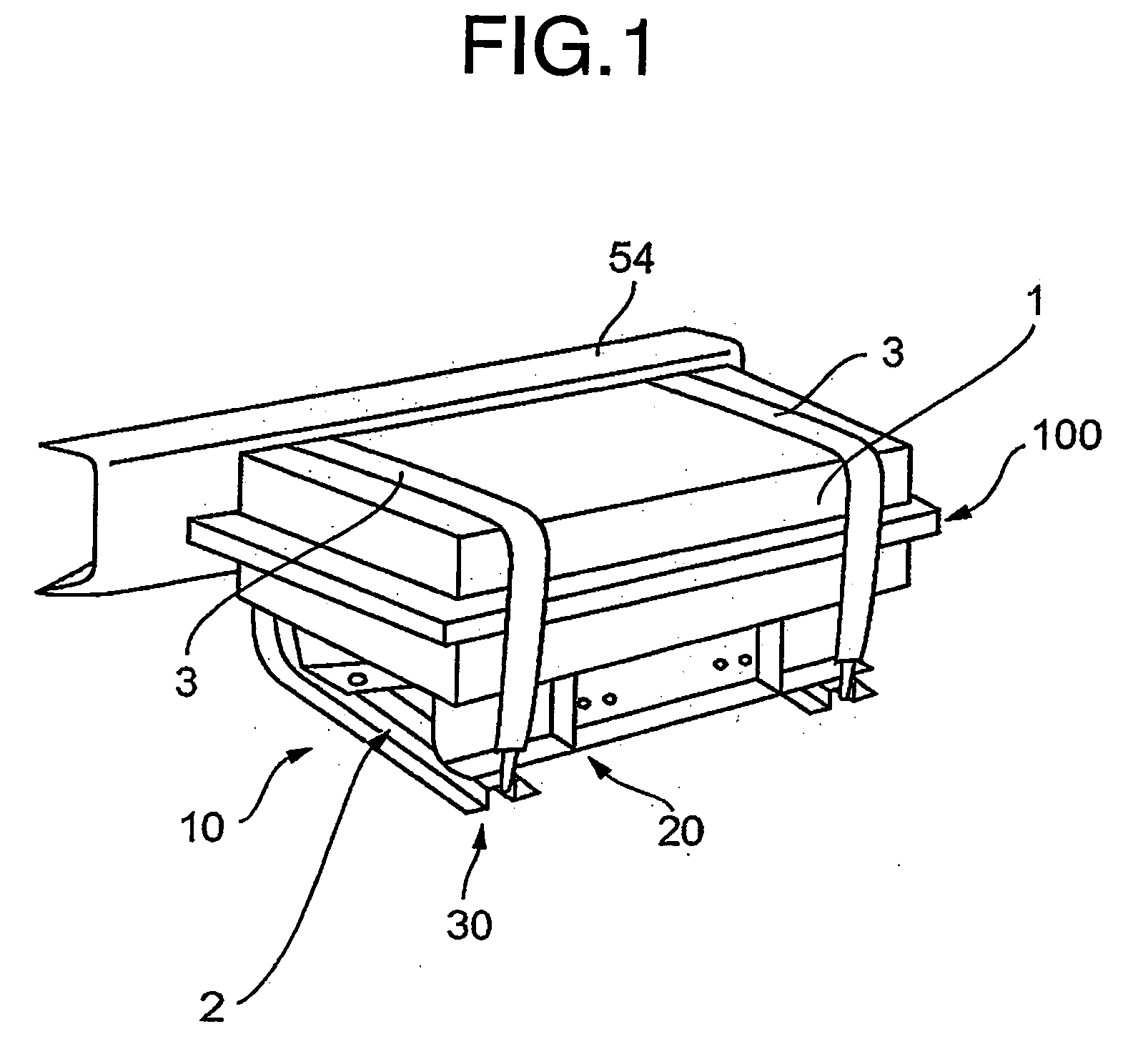
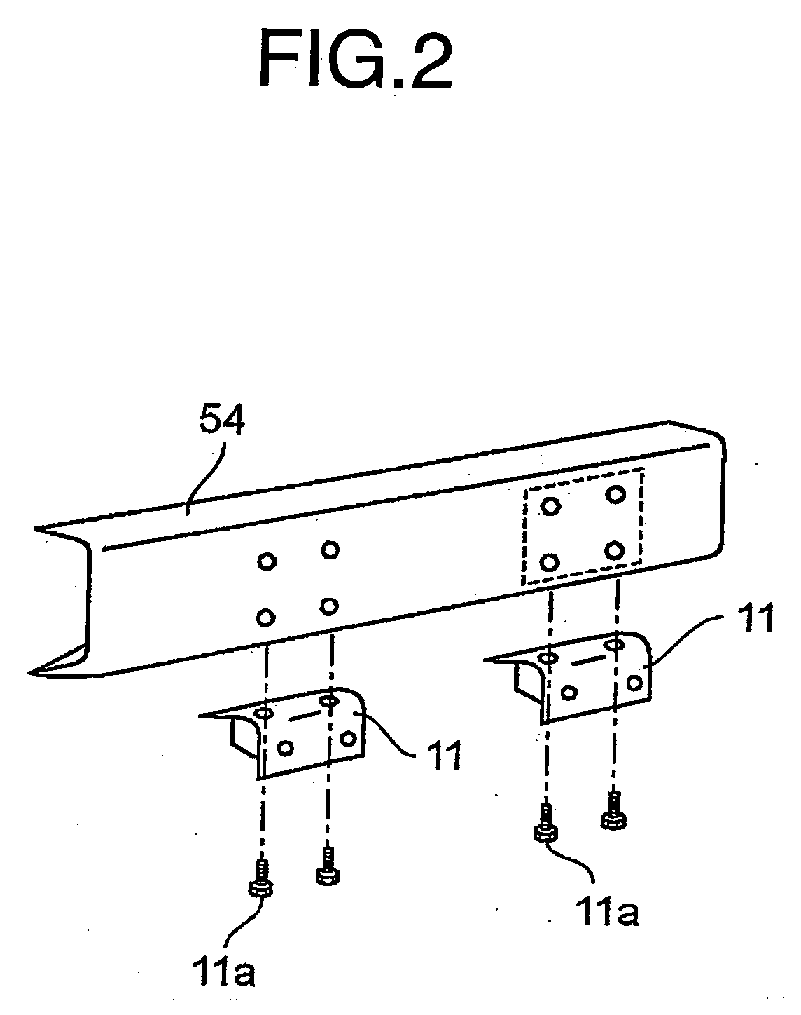
Mounting structure of electronic apparatus in vehicle

a technology for mounting structures and electronic equipment, applied in the direction of electric propulsion mounting, battery/cell mounting, transportation and packaging, etc., to achieve the effect of convenient removal, easy removal, and ease of mounting operation of the system

Inactive Publication Date: 2006-05-11
MITSUBISHI FUSO TRUCK AND BUS CORPORATION
View PDF9 Cites 33 Cited by
  • Summary
  • Abstract
  • Description
  • Claims
  • Application Information

AI Technical Summary

Benefits of technology

[0031] Further, as the battery unit is fixed to the upper flange of the second brackets and the electronic apparatus unit is fixed to the vertical walls of the second brackets, the electronic apparatus unit can be easily removed by removing the bolts fixing the same to the second brackets and sliding the electronic apparatus unit in the longitudinal direction of the vehicle when replacing the electronic apparatus unit with a new one upon occurrence of any fault in the same. Thus, replacing of the electronic apparatus unit can be performed easily without removing the battery unit from the second brackets. A mounting process of the unit can be done in reverse order.
[0032] When replacing the battery unit, the high voltage battery unit can be removed easily without removing the motor control unit from the second brackets, for the battery unit is fixed to the upper flanges of the second brackets without interfering with the motor control unit.
[0033] According to the invention, the mounting structure is composed such that the battery unit is placed on the upper surfaces of the second brackets, the electronic apparatus unit is accommodated under the battery unit between the second brackets, and the first brackets are fixed to the side of the chassis frame, so that

Problems solved by technology

In the prior art, the

Method used


Image

  • Mounting structure of electronic apparatus in vehicle
  • Mounting structure of electronic apparatus in vehicle
  • Mounting structure of electronic apparatus in vehicle

Examples


Embodiment Construction

[0046] A preferred embodiment of the present invention will now be detailed with reference to the accompanying drawings. It is intended, however, that unless particularly specified, dimensions, materials, relative positions and so forth of the constituent parts in the embodiments shall be interpreted as illustrative only not as limitative of the scope of the present invention.

[0047]FIG. 7 is a side elevation of the embodiment of a hybrid powered refrigeration car mounted with a combination of a diesel engine 60 and an electric motor 61 according to the present invention, and FIG. 8 is a plan view of the embodiment. In FIGS. 7 and 8, reference numeral 50 is a vehicle, 51 is a cabin of the vehicle 50, 54 is a pair of right and left chassis frames, 52 are front wheels, 53 are rear wheels, and 55 is a mounting space for mounting a refrigeration system.

[0048] Reference numeral 2 is a motor control unit (electronic apparatus unit of the vehicle) for controlling said motor 61 for driving...


PUM


Abstract

A structure for mounting electronic apparatuses in an electric motor-driven vehicle can be provided, in which the electronic apparatuses such as a high voltage battery unit and motor control unit can be mounted compactly in the same section occupying a minimum mounting space, allowing them to be mounted in a vehicle of rather short wheelbase, driving efficiency of the electric motor can be improved by reducing the length of cables for transferring high voltage electric power, and space for mounting the refrigerating system can be increased which eases the mounting of the refrigerating system. The structure comprises: a pair of first brackets each having a base part being fixed to the side face of a chassis frame extending in the longitudinal direction of the vehicle and an arm part extending in the lateral direction of the vehicle, a pair of second brackets fixed to the upper surfaces of said arm parts such that they extend in the longitudinal direction of the vehicle with a certain space between them, said battery unit placed on the upper surfaces of said second brackets, and said electronic apparatus unit is placed under said battery unit between said second brackets.

Description

FIELD OF THE INVENTION [0001] The present invention relates to a mounting structure of electronic apparatuses in a motor-driven vehicle which has electronic apparatuses for controlling said motor and a battery unit which constitute an electric power source for said apparatuses. DESCRIPTION OF THE RELATED ART [0002]FIG. 9 is a plan view of a hybrid powered refrigeration car mounted with a diesel engine / electric motor combination. [0003] In the drawing, reference numeral 51 is a cabin, 54 is a chassis frame, 53 are rear wheels, 55 is a mounting space for a refrigeration system. [0004] Reference numeral 2 is a motor control unit to control a motor for driving the car, 1 is a high voltage battery unit constituting the electric source for said motor and motor control unit. Said high voltage battery unit 1 is attached to a side part of the chassis frame 54 between front wheels not shown in the drawing and the rear wheels 53. The motor control unit 2 is located under the mounting space 55....

Claims


Application Information

Patent Timeline
IPC IPC(8): B60K1/00B60R16/04
CPCB60K1/04B60L11/18B60L11/1877B60L2200/36B60R16/04Y02T10/7005Y02T10/705Y02T90/124B60L50/60B60L50/66Y02T10/70B60K6/28B60P3/20B60Y2200/91B60Y2200/92Y02T90/12
Inventor YOSHIDA, KEI
Owner MITSUBISHI FUSO TRUCK AND BUS CORPORATION
Why Eureka
Try Eureka