VacuMag magnetic separator and process

a magnetic separator and vacuum magnet technology, applied in the field of magnetic separators, can solve the problems of limited space, increased cost of impounding, and low loss of fly ash ignition (loi) of fly ash,

Inactive Publication Date: 2006-05-11
EXPORTECH CO INC
View PDF12 Cites 13 Cited by
  • Summary
  • Abstract
  • Description
  • Claims
  • Application Information

AI Technical Summary

Benefits of technology

[0018] The present invention pertains to an apparatus for separating a stream of particles with individual sizes smaller than 300 μm and magnetic properties ranging from collective magnetism as in ferromagnetism to paramagnetism to diamagnetism. The apparatus comprises a plurality of stages for separating a stream of particles. The apparatus comprises a magnetic component producing a magnetic force associated with each stage. The apparatus comprises an aerodynamic component producing an aerodynamic force associated with each stage, where the more magnetic component or components of a feed of particles for each stage is separated and either or both the less magnetic product and the more magnetic product of each stage are the feed for separate succeeding stages with each stage and where the magnetic and aerodynamic forces along with gravimetric forces of each stage are chosen to separate more strongly magnetic particles fr...

Problems solved by technology
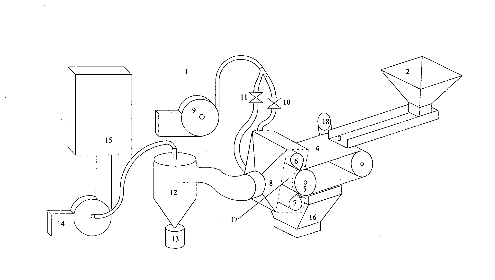
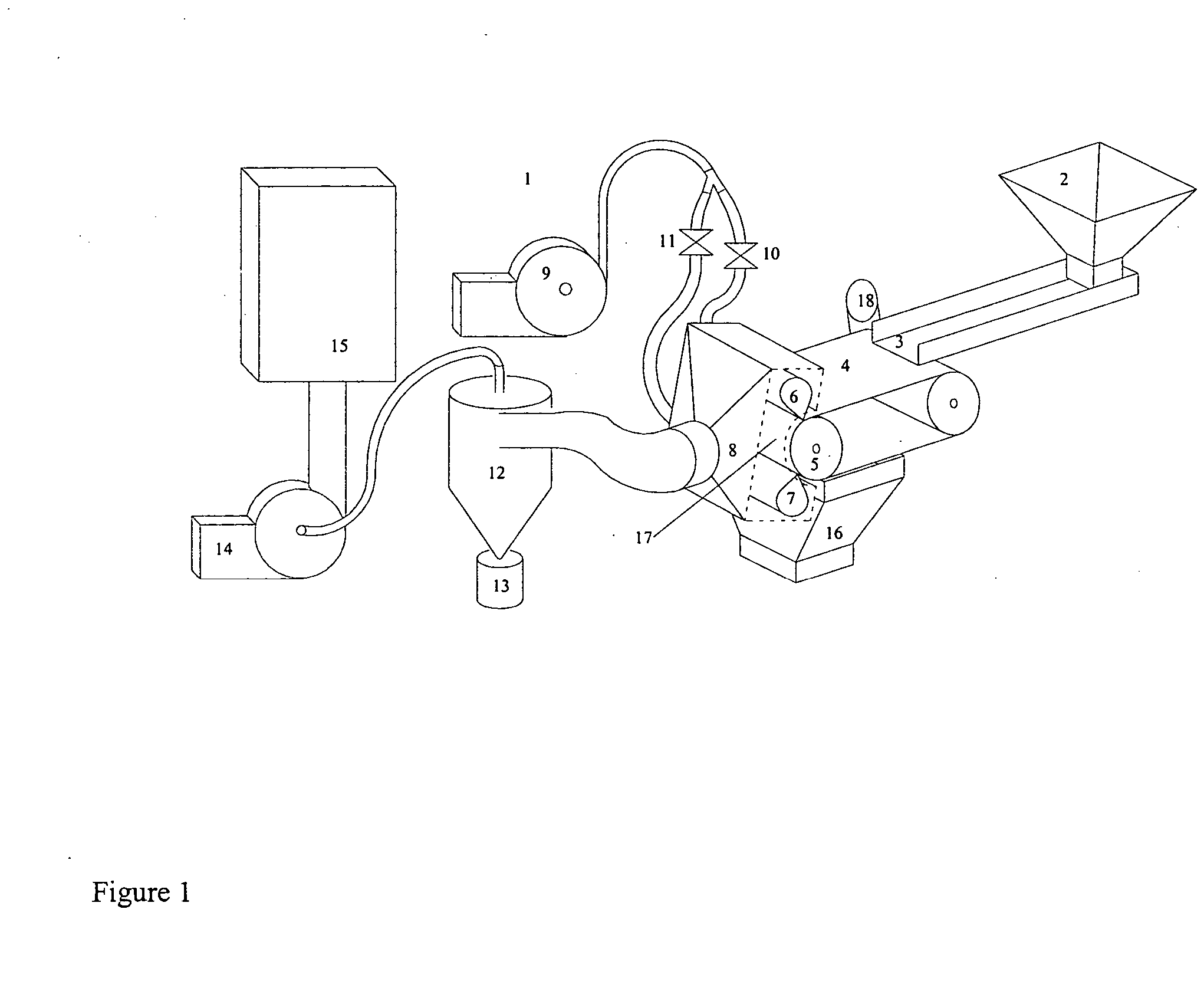
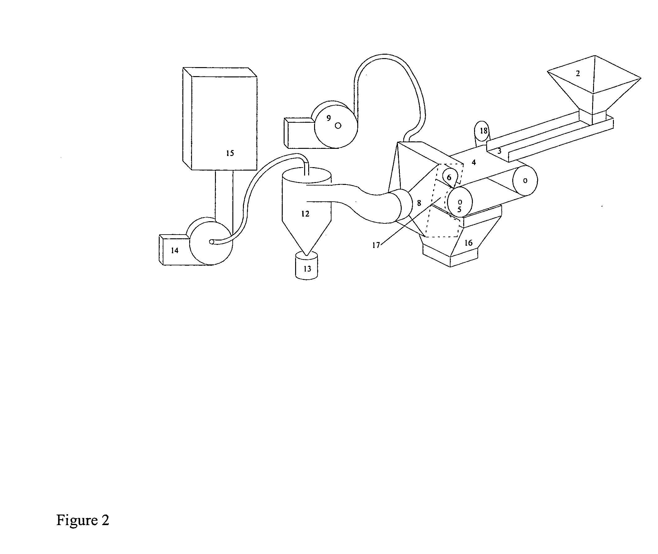
A factor limiting the use of some fly ashes in Portland cement is that the Loss on Ignition (LOI) of the fly ash must be below 6.0% (ASTM C618-99).
Impoundment is an expense to power plants and can be a problem for plants with limited space.
In practical applications, however, the imposed force is never the only force experienced by the particles.
Therefore, electrostatic forces are difficult to control and use to separate a broad range of fine particles.
If dry particles are to be recovered, the wetted particles must then...

Method used


Image

  • VacuMag magnetic separator and process
  • VacuMag magnetic separator and process
  • VacuMag magnetic separator and process

Examples


examples

[0054] In the following examples, gas drag forces were used to mix particles, disperse agglomerates, and remove diamagnetic and weakly paramagnetic particles from the conveyor belt. In other tests without the gas drag forces, a layer of fly ash collected on the belt up to 2 mm thick and did not fall off even after passing beneath the magnetic mechanism. The agglomerating forces and attractive forces to the belt were stronger than gravity and centrifugal forces that would pull the particles off of the belt. However, in none of the examples cited below which incorporated gas drag forces did a significant mass of particles stick to the belt. The less magnetic fractions were lifted off the belt and carried away by the gas stream, and the magnetic fractions were carried to the bottom of the magnetic mechanism by the belt where they fell off.

[0055] Three dry (less than 0.3% moisture) samples of fly ash from an Eastern U.S. pulverized coal fired power plant were separated using a separato...


PUM

PropertyMeasurementUnit
Lengthaaaaaaaaaa
Thicknessaaaaaaaaaa
Sizeaaaaaaaaaa

Abstract

An apparatus for separating a stream of particles with individual sizes smaller than 300 μm and magnetic properties ranging from collective magnetism as in ferromagnetism to paramagnetism to diamagnetism. The apparatus includes a plurality of stages for separating a stream of particles. The apparatus includes a magnetic component producing a magnetic force associated with each stage. The apparatus includes an aerodynamic component producing an aerodynamic force associated with each stage, where the more magnetic component or components of a feed of particles for each stage is separated and either or both the less magnetic product and the more magnetic product of each stage are the feed for separate succeeding stages with each stage and where the magnetic and aerodynamic forces along with gravimetric forces of each stage are chosen to separate more strongly magnetic particles from less magnetic particles.
A method for separating a stream of particles with individual sizes smaller than 300 μm and magnetic properties ranging from collective magnetism as in ferromagnetism to paramagnetism to diamagnetism.

Description

[0001] This invention was made with Government support under Grant DMI-9983422 awarded by the National Science Foundation. The Government has certain rights in this invention.BACKGROUND OF THE INVENTION [0002] 1. Field of the Present Invention [0003] This invention relates to magnetic separators particularly for fine particles. More specifically, a combination of forces are used to separate dry particles of different magnetic susceptibilities. The forces include magnetic forces along with suction, blowing, or a combination of suction and blowing. The magnetic force attracts and holds the ferromagnetic and strongly paramagnetic particles to the conveying surface while the suction and / or blowing lifts the diamagnetic and weakly paramagnetic particles off of the conveying surface. Thus a separation based on the magnetic properties of the particles is accomplished and agglomerating forces are overcome. [0004] 2. Description of the Prior Art [0005] Fly ash from coal fired power plants ha...

Claims


Application Information

Patent Timeline
IPC IPC(8): B03C7/00B03C1/00C02F1/48B07C5/00
CPCB03C1/08B07C5/344C02F1/488
Inventor BRANDNER, EDWARD D.JAMISON, RUSSELL E.
Owner EXPORTECH CO INC
Why Eureka
Try Eureka