Clamping device for processing work pieces

a technology for processing work pieces and clamping elements, which is applied in the direction of forging/hammering/hammering apparatus, forging/hammering/pressing machines,auxillary welding devices, etc. it can solve the problems of static redundancy, complex, expensive and inflexible, and the type of fixing and clamping elements are tailored specifically for a component. it is easy to maintain control of such a welding process, improve the joint location, and control the joint gap locally

Inactive Publication Date: 2006-05-11
DAIMLER AG
View PDF10 Cites 13 Cited by
  • Summary
  • Abstract
  • Description
  • Claims
  • Application Information

AI Technical Summary

Benefits of technology

[0012] It is the task of the invention to develop a device for processing work pieces, of which the clamping technique allows a high working quality and, with respect to the work piece geometry, makes possible a high flexibility in processing.
[0015] By the appropriate design and arrangement of the clamping fingers and the clamping roller, joint gaps can be produced and maintained between the work pieces over a large surface area. The geometry of the joint gap can be well controlled. The invention unites the advantages of clamp finger and clamp roller, so that there is free access for a tool at a processing location, in particular in the area exposed to view no scratch and / or marking of the clamp finger occurs upon the work piece and only small force applications need be applied to the work piece to be processed. Therewith there results, during use of this accompanying or traveling clamping system, an improved controllability of joint gaps over relatively large surfaces.
[0017] The invention makes it possible to control a joint gap locally at a joint location better than with conventional accompanying solutions. The invention further makes possible the realization of light weight or simplified construction techniques, such as for example reduced flange breadth on body parts. The inventive clamping process is not limited to flanges but is applicable to the entire work piece. Thereby there results a high flexibility with regard to the possible variability of the target component. Particularly in the provision of planar or flat processing patterns there results in the employment of the invention a good accessibility of the welding tool to a clamping point from different directions. Welding patterns spreading out geometrically in a plane, such as circles, ovals or brackets, require in comparison to conventional, for example conventional processing lens produced dash seams, a more flat controlling of the joint gap. In particular in welding processes, with specific or targeted intervention in the beam positioning of the laser beam, the results, due to the flexible clamping, new possibilities to carry out the welding process. Further, with the invention it is possible to minimize imprints from the clamping elements on one of the two work piece surfaces, in particular component surfaces intended to be visible.

Problems solved by technology

This type of fixing and clamping elements are tailored specifically for a component, are complicated, expensive and inflexible.
Due to the large number of clamping elements there are many sources of possible faults, so that it is more difficult to maintain control over such a welding process.
If work pieces are simultaneously clamped in all locations, then a static redundancy results.
Further, for containing the static redundancy, high clamping forces are necessary.
The problem with all these systems is the controlling or containment of the joint gap with increasing distance from the clamping location.
Known clamping systems with clamping roller s have construction dictated limitations in the accessibility of welding tools at a welding location.
When welding behind a roller the welding location is so far removed from the clamping location that a verifiable welding process can no longer be reliably ensured due to uncontrollable widening of the joint cap.
It is difficult for the roller to control the joint gap beside the roller with increasing distance from the roller, which makes impossible a process of reliable welding of geometric welding patterns, such as for example circular seams.
A disadvantage in the employment of clamping fingers is the difficult to control, and hardly to be guaranteed, joint gap relationships or behavior with increasing distancing from the clamping point.
A further disadvantage of purely finger clamping systems is the application of force upon a work piece to be joined respectively due to the friction between the clamping finger and the work piece.
This disadvantage occurs above all in work pieces which require greater clamping forces and in which the clamping forces are built up locally upon a joint location, wherein during a robot movement the clamping fingers are removed from the respective work piece.
Further, clamping fingers cause grooves and scratch marks, which compromise or preclude a visual presentability of a joint location.
This device is voluminous, elaborate and expensive and limited in its employability.

Method used


Image

  • Clamping device for processing work pieces
  • Clamping device for processing work pieces
  • Clamping device for processing work pieces

Examples


Embodiment Construction

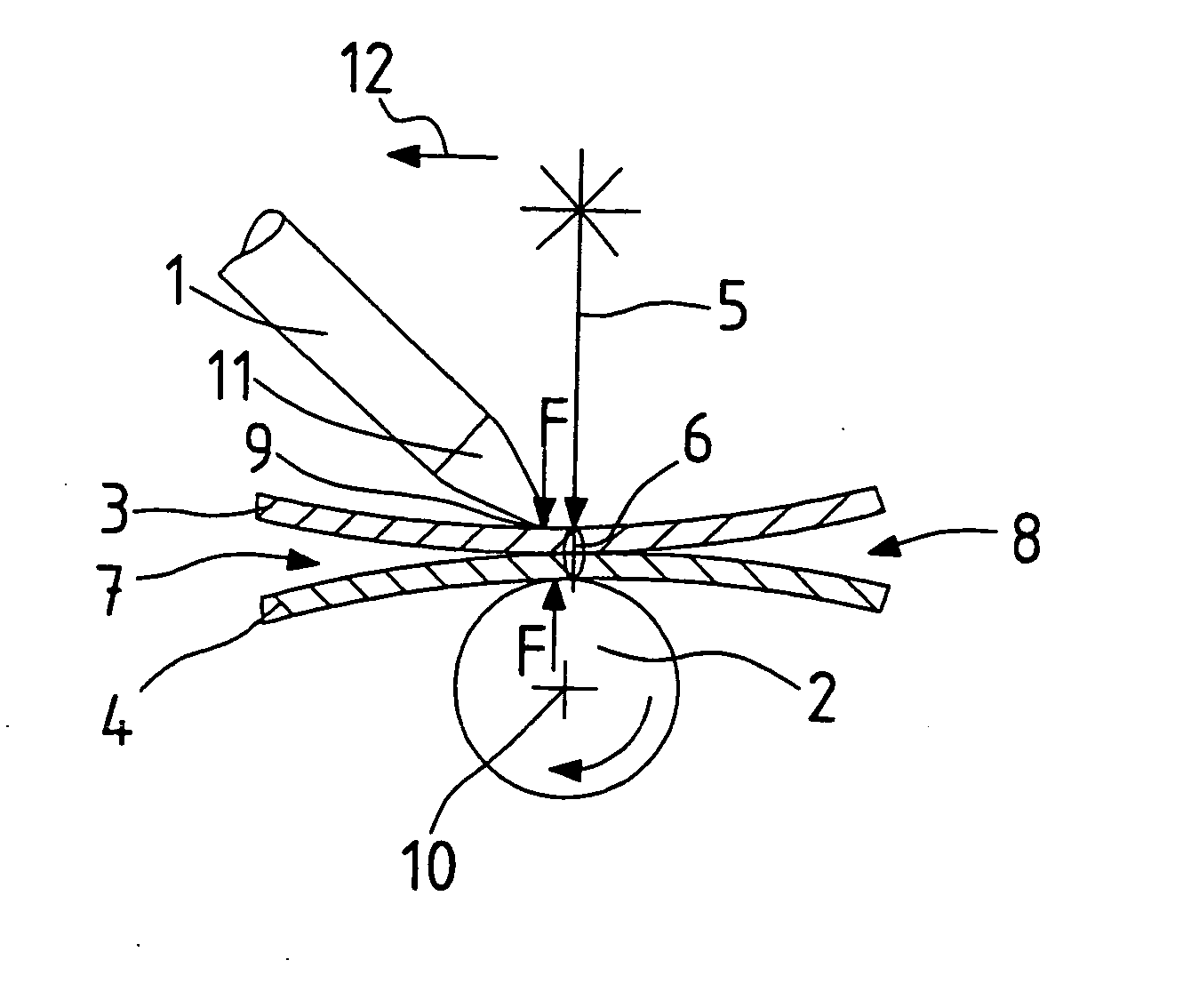
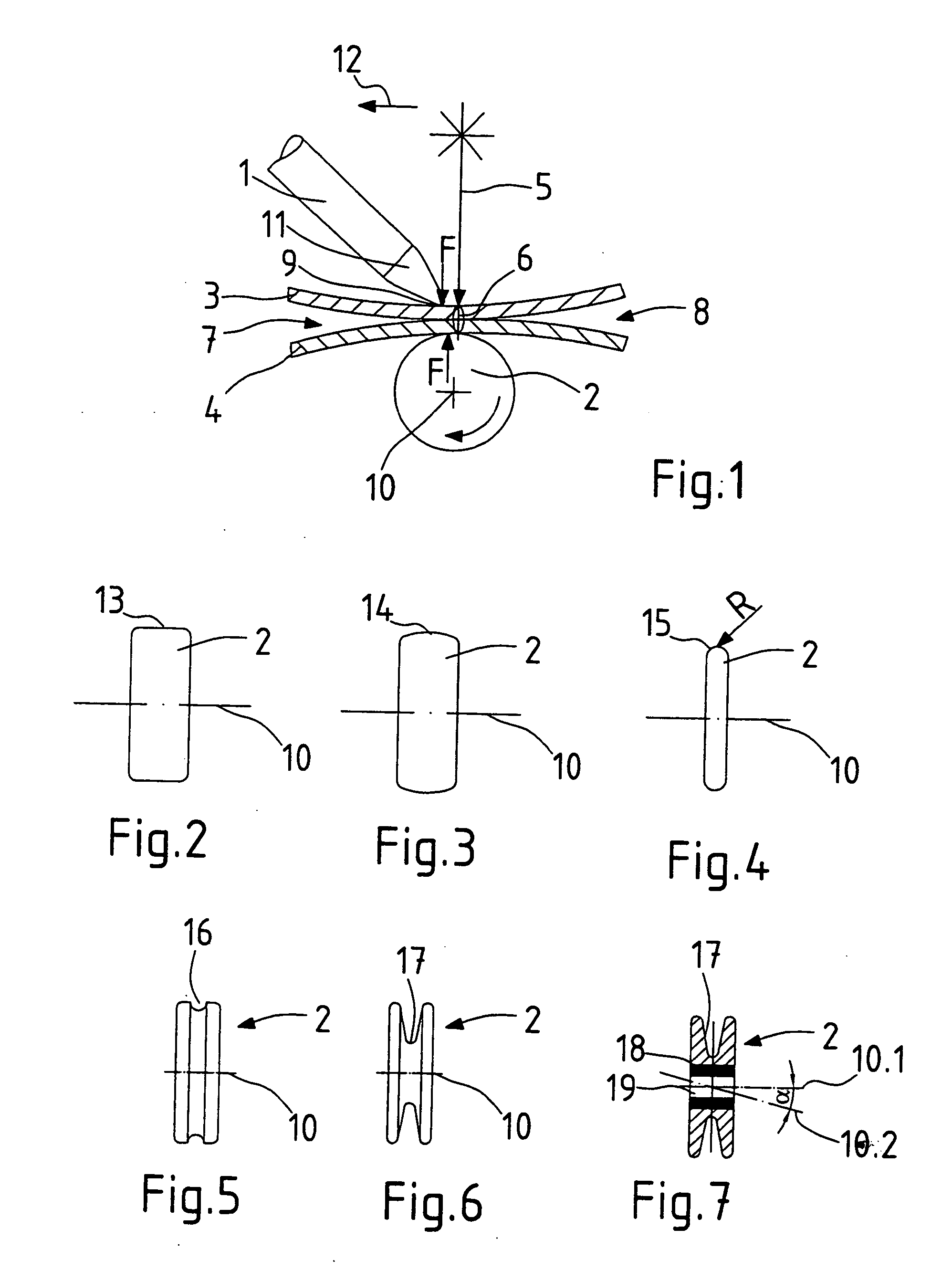
[0029]FIG. 1 shows a principle schematic of a clamping device with a clamping finger 1 and a clamping roller 2 for clamping of two sheets 3, 4 during welding with a laser beam 5. The laser beam 5 impinges perpendicularly upon the surface of the sheet 3. The clamping device is activated or operated, that means, clamp fingers 1 and clamping roller 2 are positioned against the sheets 3, 4 and they exercise upon the sheets 3, 4 a clamping force, which presses together the sheets 3, 4 at the welding location 6. On the welding location 6 the sheets 3, 4 lie tight against each other. In the absence of the effect of the clamping force gaps 7, 8 exists between the sheets 3, 4 outside of the welding location 6. The clamping device, inclusive of actuating process, can be provided on an arm of a robot, or in the clamping finger 1 and the clamping roller 2 can be applied and retracted for moving of the clamping location 9 to clamping location 9 on the sheets 3, 4. The movement of clamping positi...


PUM

PropertyMeasurementUnit
clamp forceaaaaaaaaaa
gap widthaaaaaaaaaa
power intensityaaaaaaaaaa

Abstract

The invention concerns a clamping device for processing, in particular welding, of work pieces. It is the task of the invention to develop a device for processing work pieces, of which the clamp technique enables a high processing quality and, with respect to the work piece geometry, enables a high flexibility of the process. According to the invention, the clamp device for processing of work pieces comprises at least one first clamp element and at least one second clamp element, between which a work piece is held, wherein a tool is movable relative to the work piece, wherein the first clamp element is in the form of a clamp finger (1, 24) and engages on the side of the work piece (3) which is the side upon which the tool (5) acts, and further, that the second clamp element is in the form of a clamp roller (2) and lies against the work piece (4) on the side opposite to the tool (5).

Description

BACKGROUND OF THE INVENTION [0001] 1. Field of the Invention [0002] The invention concerns the clamping device for processing work pieces according to the pre-characterizing portion of Claim 1. [0003] 2. Related Art of the Invention [0004] When joining two or more work pieces by welding with high power intensity, such as during laser welding, electron beam welding or plasma welding, the joint gaps between the work pieces may not exceed permissible widths. In maximal permissible joint gap if a function of the welding process employed, the composition of the work pieces, and the construction specifications. For establishing and containing the joint gap within requirements, clamping devices are employed, which in the optimal case keep the joint gap in the area of the welding location as small as possible. [0005] A fixed or stationary clamping technique with non-moving fixing and clamping elements for use in the welding of work pieces is known. A multitude of clamping element sites ensu...

Claims


Application Information

Patent Timeline
Patent Type & Authority Applications(United States)
IPC IPC(8): B23K26/20B23K26/02B23K26/08B23K26/22B23K26/24B23K26/32B23K26/42B23K37/04B25B11/00
CPCB23K26/023B23K26/083B23K26/22B23K26/246B23K26/3293B23K37/0408B23K37/0435B23K2201/006B23K2201/18B23K2201/34B23K26/037B23K26/244B23K2101/006B23K2101/18B23K2101/34B23K2103/08
Inventor PFIZ, DANIEL
Owner DAIMLER AG
Why Eureka
Try Eureka