Focused ion beam system

a technology beams, applied in the field of focused ion beams, can solve the problems of low efficiency, low efficiency, and inability to perform high-contrast imaging, and achieve the effect of sacrificing the life of the system

Inactive Publication Date: 2006-05-11
JEOL LTD
View PDF4 Cites 21 Cited by
  • Summary
  • Abstract
  • Description
  • Claims
  • Application Information

AI Technical Summary

Benefits of technology

[0040] It is an object of the present invention to provide a FIB system capable of making the best use of the theoretical advantages of the three-lens type using an acceleration-type objective lens without sacrificing the life of the system.
[0046] In this embodiment of the present invention, the ion beam is extracted from the ion source by the extraction electrode. The angular aperture of the extracted ion beam is controlled by the condenser lens. The ion beam having the certain angle of radiation is taken out from the ion beam, whose angular aperture has been controlled by the condenser lens, by the current-limiting aperture. The ion beam is corrected for aberrations by the electrostatic aberration-correcting means without varying the amount of current of the ion beam passed through the current-limiting aperture. The ion beam that has been corrected for aberrations by the electrostatic aberration-correcting means is focused onto the specimen by the electrostatic objective lens. The electrostatic aberration-correcting means located behind the current-limiting aperture is controlled with the polarity with which charged particles are decelerated. The electrostatic objective lens is controlled with the polarity with which the charged particles are accelerated.
[0049] The invention described so far yields the following advantages.
[0051] Therefore, the background current contained in the beam current is reduced. This permits high-contrast, high-resolution imaging which should be anticipated when an acceleration-type objective lens is used. Furthermore, it is not necessary to thin the current-limiting aperture. Consequently, it is possible to make the best use of the theoretical advantages of the three-lens type using an acceleration-type objective lens without sacrificing the life of the system.
[0052] The provision of the deflection means for scanning the ion beam, whose angular aperture has been controlled, over the specimen and the image creation means for detecting secondary charged particles produced from the specimen by the scanning and creating an image corresponding to the particles enables high-contrast, high-resolution SIM (scanning ion microscope) imaging.
[0054] Therefore, the background current contained in the beam current is reduced. This permits high-contrast, high-resolution imaging which should be anticipated when an acceleration-type objective lens is used. In addition, it is not necessary to thin the current-limiting aperture. Hence, the best use of the theoretical advantages of the three-lens type using an acceleration-type objective lens can be made without sacrificing the life of the system.

Problems solved by technology

This makes it impossible to perform high-contrast, high-resolution imaging which should be expected when an acceleration-type objective lens is used.
Consequently, as the diameter of the current-limiting aperture is reduced, the contrast and resolution deteriorate.
However, the current-limiting aperture is thinned.
However, since the current-limiting aperture 50 is thin, the life is extremely shortened, causing a problem in terms of practicality.
Accordingly, if the thickness is increased, the life will be increased but improvement of the performance cannot be expected.
Conversely, if the thickness is reduced, improvement of the performance can be expected but the life will be shortened.
In consequence, the components of the charged particles produced at the edge of the current-limiting aperture cannot reach the objective lens, producing good results.
For this reason, as the diameter of the current-limiting aperture is reduced, the contrast and resolution deteriorate.
However, since the current-limiting aperture 50 is thick, the life is extremely shortened, causing a problem in terms of practicality.

Method used


Image

  • Focused ion beam system
  • Focused ion beam system
  • Focused ion beam system

Examples


first embodiment

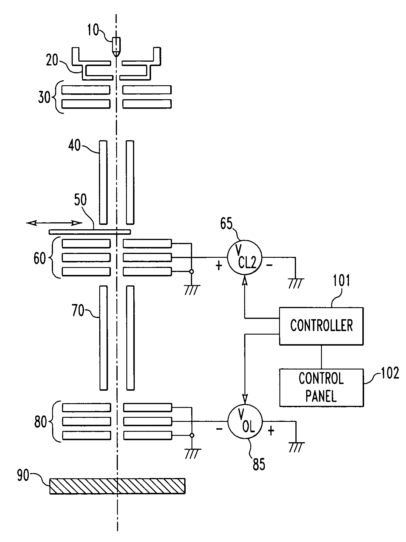
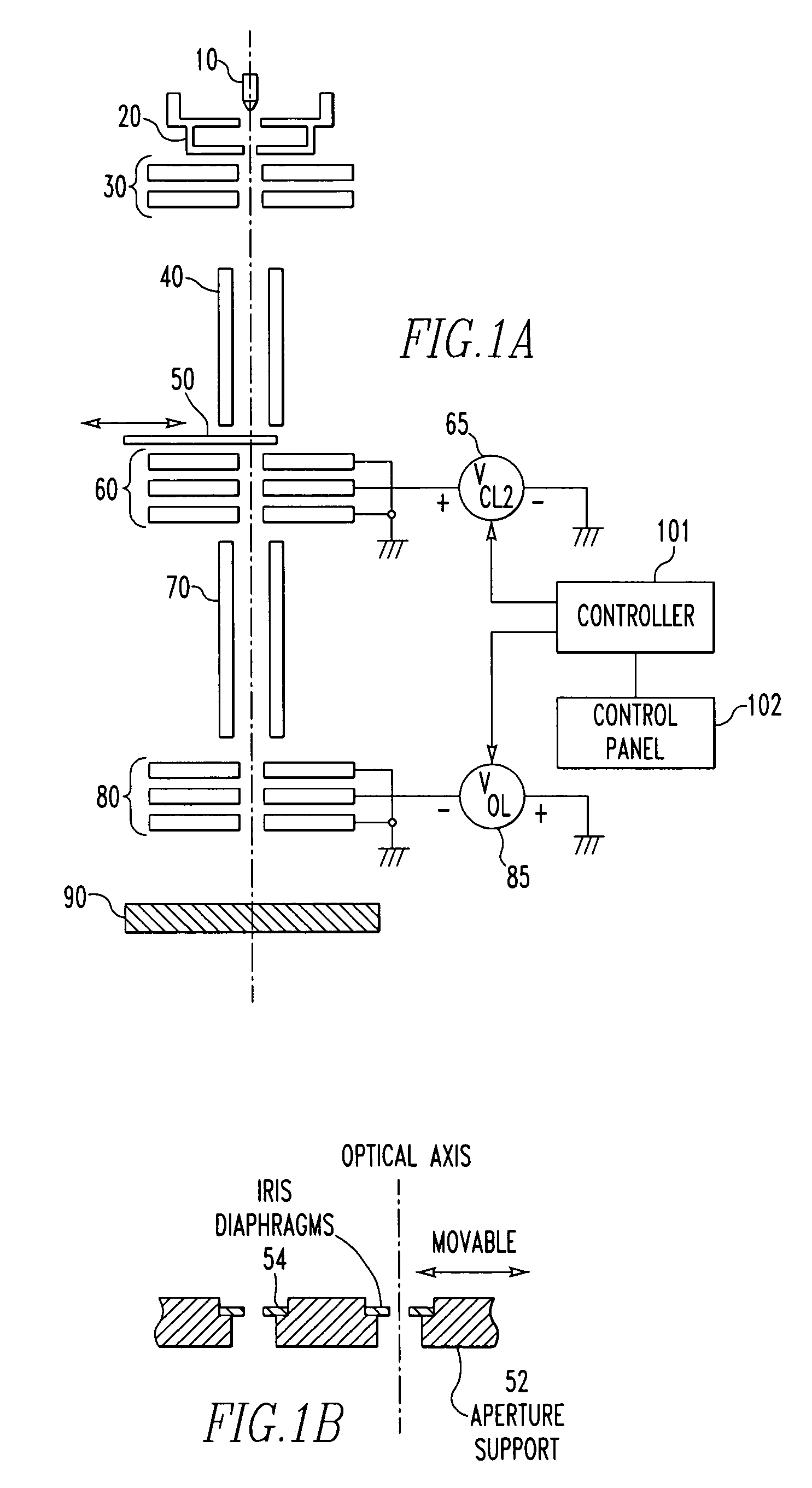
[0064] The mechanical and electrical configurations of the whole of a focused ion beam (FIB) system according to a first embodiment of the present invention is first described by referring to FIGS. 1A and 1B. In FIG. 1A, fundamental members for holding various components, such as microscope column and frame, are omitted. The illustrated FIB system is of the three-lens type.

[0065] Referring to FIG. 1A, an emitter 10 forms a main portion of an ion source (e.g., a liquid metal ion source (LMIS) or gas phase ion source (GFIS)) for producing ions. An extraction electrode 20 extracts an ion beam from the emitter 10. A condenser lens (first condenser lens) 30 controls the angular aperture of the extracted ion beam. A beam aligner 40 deflects the ion beam, whose angular aperture has been controlled by the condenser lens 30, such as for alignment of the beam. A current-limiting aperture 50 takes out an ion beam having a certain angle of radiation from the ion beam whose angular aperture has...

embodiments

[0091] Most of the kinetic energies of charged ions produced by sputtering are considerably lower as compared with the accelerating voltage. The objective lens is of the acceleration type, while the angular aperture control lens is of the deceleration type. Therefore, charged particles arising from the edge of the current-limiting aperture cannot pass through the angular aperture control lens acting to decelerate ions. Consequently, the background current Ibck contained in the whole beam current Iexp of the ion beam decreases. This enables high-contrast, high-resolution imaging which should be expected when an acceleration-type objective lens is used. This has been confirmed also experimentally. Furthermore, the current-limiting aperture 50 has normal thickness and so no problem occurs in terms of life. That is, it has been confirmed that a FIB system capable of making the best use of the theoretical advantages of the three-lens type using an acceleration-type objective lens can be ...

second embodiment

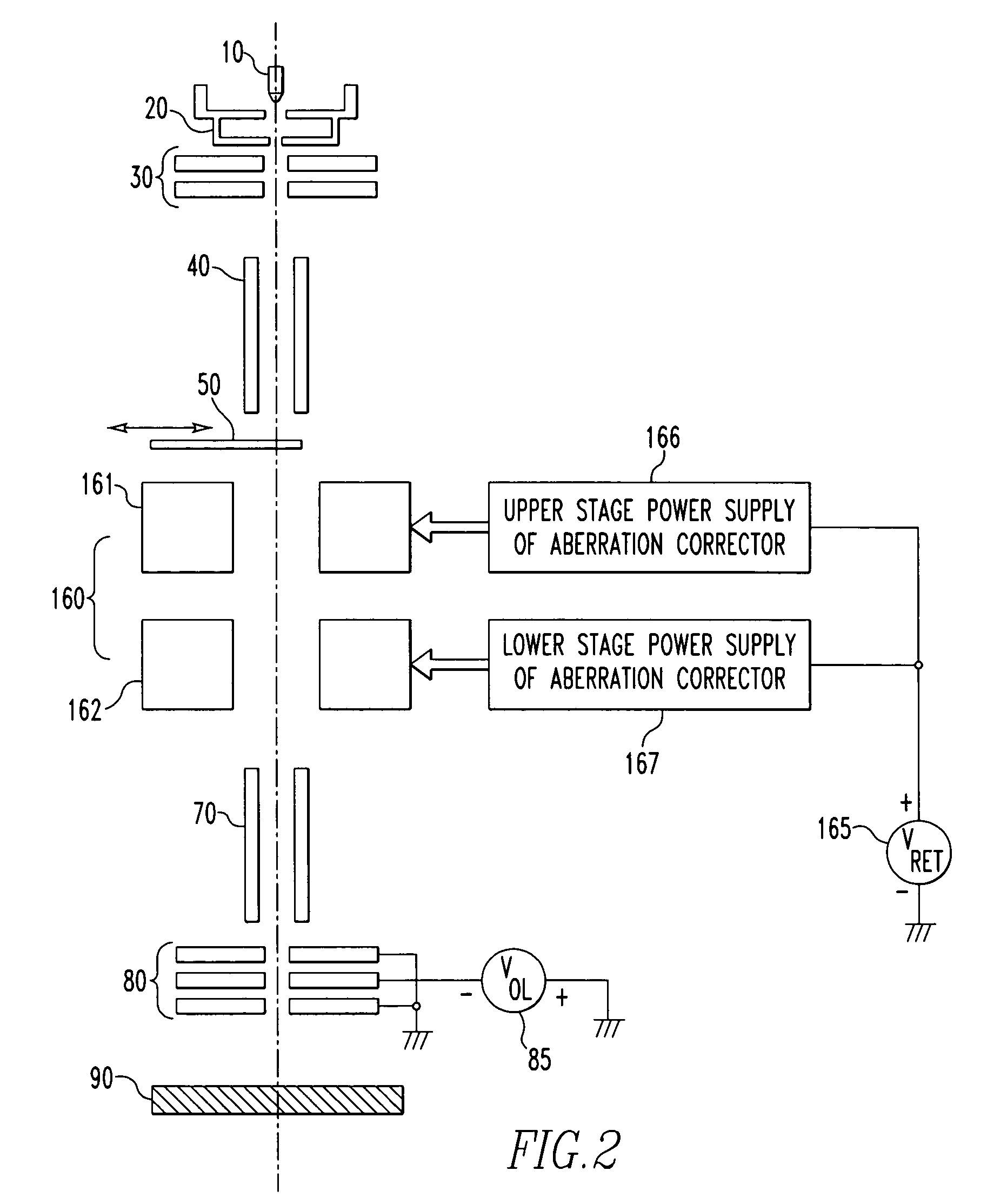
[0093] The mechanical and electrical configurations of the whole FIB system according to the second embodiment is described by first referring to FIG. 2. In FIG. 2, fundamental members for holding various components, such as microscope column, and pedestal are omitted.

[0094] Shown in FIG. 2 is a FIB system of the three-lens type having a condenser lens, an aberration corrector, and an objective lens. In this case, the aberration corrector having lens components is also regarded as a lens.

[0095] An emitter 10 forms a main portion of an ion source. An extraction electrode 20 extracts an ion beam from the emitter 10. A condenser lens (first condenser lens) 30 controls the angular aperture of the extracted beam. A beam aligner 40 deflects the ion beam whose angular aperture has been controlled by the condenser lens 30, such as for alignment of the beam. A current-limiting aperture 50 takes out an ion beam having a certain angle of radiation from the ion beam whose angular aperture has...


PUM


Abstract

A focused ion beam (FIB) system has an ion beam from an ion source, a condenser lens, a current-limiting aperture, an electrostatic angular aperture control lens, an electrostatic objective lens, and a controller which controls the angular aperture control lens with a polarity with which charged particles are decelerated and the objective lens with a polarity with which the charged particles are accelerated.

Description

BACKGROUND OF THE INVENTION [0001] 1. Field of the Invention [0002] The present invention relates to a focused ion beam (FIB) system of the three-lens type. [0003] 2. Description of Related Art [0004] Many focused ion beam systems now available in the market are fundamentally equipped with two lenses: an electrostatic condenser lens for controlling the angular aperture of an ion beam and an electrostatic objective lens for focusing the ion beam onto a specimen. [0005] On the other hand, there exist focused ion beam systems equipped with three lenses, though the number is limited. [0006]FIGS. 4A and 4B show a focused ion beam system of the latter type. The system has an emitter 10 having a front-end portion into which a substance to be ionized is supplied, an extraction electrode 20 for extracting the particles ionized in the front-end portion of the emitter 10 as an ion beam, a condenser lens (first condenser lens) 30 for controlling the angular aperture of the extracted ion beam, a...

Claims


Application Information

Patent Timeline
Patent Type & Authority Applications(United States)
IPC IPC(8): H01J37/08
CPCH01J37/09H01J37/12H01J37/28H01J2237/0455H01J2237/0458H01J2237/12H01J2237/2487H01J2237/31749
Inventor SAKAGUCHI, KIYOSHI
Owner JEOL LTD
Why Eureka
Try Eureka