Illuminating device and method of fabricating the same

a technology of illuminating devices and manufacturing methods, which is applied in the direction of vehicle spotlighting, semiconductor devices for light sources, lighting and heating apparatus, etc. it can solve the problems of large number of components, increase in manufacturing costs, and complex construction of such devices, so as to achieve low manufacturing costs of illuminating devices, reduce thickness of illuminating devices, and achieve low manufacturing costs.

Inactive Publication Date: 2006-05-11
ALPS ALPINE CO LTD
View PDF9 Cites 29 Cited by
  • Summary
  • Abstract
  • Description
  • Claims
  • Application Information

AI Technical Summary

Benefits of technology

[0025] According to this construction, since the transfer film having the insulating layer and the conductive layer and not having the reflecting film is used, the illuminating device which does not have the reflecting film on the receiving-portion-forming surface of the lens except the inner surface of the receiving portion can be fabricated. The other effects are similar to those of the third aspect.
[0026] Since the illuminating device according to the present invention includes a light emitting diode (LED); a lens having a receiving portion for the light emitting diode to diffuse light irradiated from the light emitting diode; and a wiring member having a conductive portion which is electrically connected to the light emitting diode, the LED can be received in the receiving portion formed in one surface of the lens and thus the total thickness of the illuminating device becomes a sum of the thickness of the lens and the thickness of the wiring member. Thus, the thickness of the illuminating device can be remarkably reduced. Further, the light irradiated from the LED can be directed to the light emitting surface of the lens without waste and manufacturing cost of the illuminating device can be reduced due to reduction of the setting number of LEDs. In addition, if the switch is manipulated by pressing the lens, a special member for manipulating the switch can be omitted and thus small-size and low manufacturing cost of the illuminating device can be accomplished.
[0027] In the method of fabricating the illuminating device according to the present invention, since the lens and the film-shaped wiring member are integrally formed upon the injection molding of the resin mold, the illuminating device can be easily fabricated, compared with the case where members are individually fabricated and then integrally formed. Further, since the LED is received in the receiving portion and the film-shaped conductive portion transferred from the transfer film is electrically connected to the terminal portion of the LED after fabricating the resin mold, excessive force and heat is not applied to the LED and thus a product can be fabricated with a quality fabrication.

Problems solved by technology

Accordingly, the number of components is large, the construction thereof is complex, and a manufacturing cost is like to increase.
Furthermore, since the valve lamp 105 has a large size and a heating value, and should be spaced apart from the cover 107 which functions as the lens at a predetermined distance, the thickness T of the apparatus increases and limits the flexibility of design in the vehicle.
In addition, a user needs to replace the valve lamp 105, and thus, adding an increase in cost.
However, the LED was not used as a light source of an illuminating device included in a vehicle, such as a room lamp or a map lamp.
However, it can not be sufficiently achieved to reduce the thickness of the illuminating device and manufacturing cost thereof by only using the LED instead of the valve lamp 105.
Therefore, the reduction in thickness can not be significantly obtained.

Method used


Image

  • Illuminating device and method of fabricating the same
  • Illuminating device and method of fabricating the same
  • Illuminating device and method of fabricating the same

Examples


first embodiment

[0052] As shown in FIG. 5, the illuminating device 1c according to the present embodiment includes the external connector 21 which is integrally provided with the lens 2 and electrically connects the lens 2 with an external device such as an LED 3 and a power supply circuit. The external connector 21 includes a main body 21a made of resin and a terminal portion 21b set in the main body 21a, and the terminal portion 21b is electrically connected to the conductive portion 4a. The main body 21a may be formed of the same kind of a resin material as the material forming the lens 2 or a kind of a resin material different from the material forming the lens 2. In case the main body 21a is formed of the same kind of the resin material as the material forming the lens 2, the lens 2 and the main body 21a may be simultaneously formed in a mold. On the other hand, in case the main body 21a is formed of a kind of resin material different from the material forming the lens 2, the lens 2 and the ma...

second embodiment

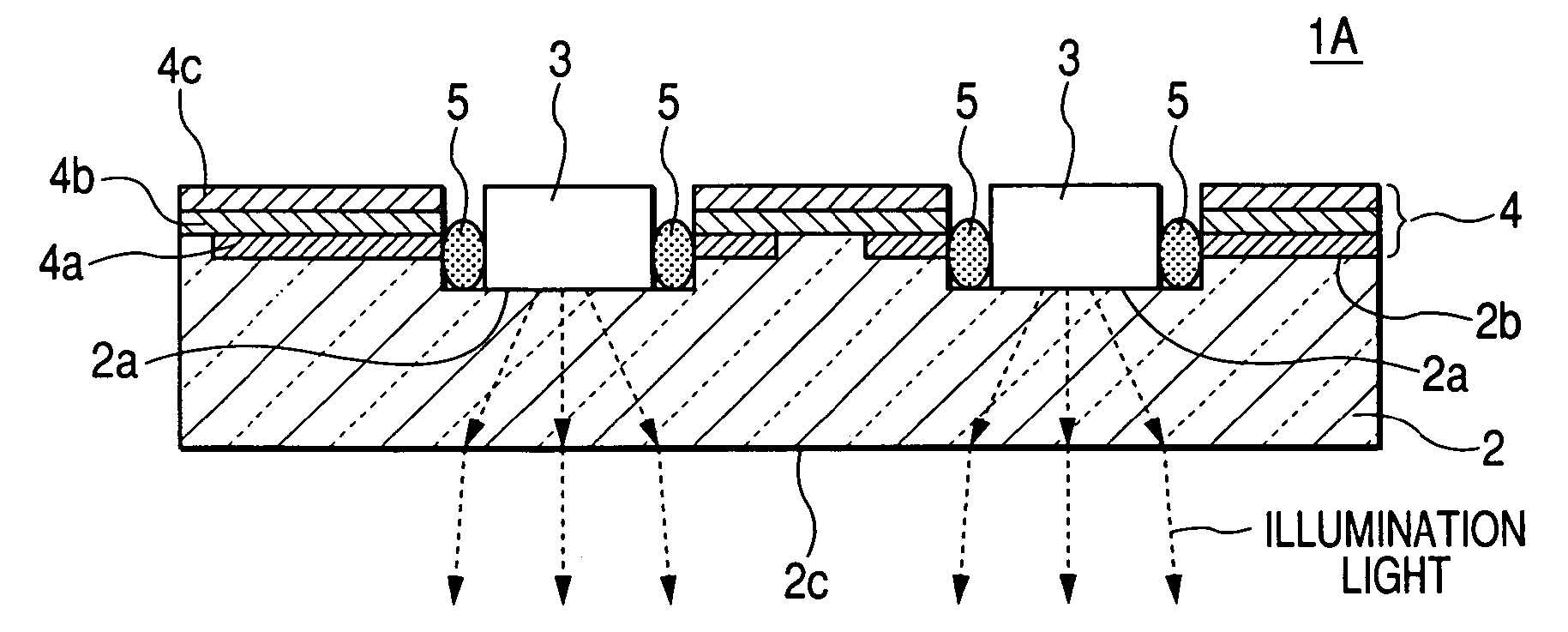
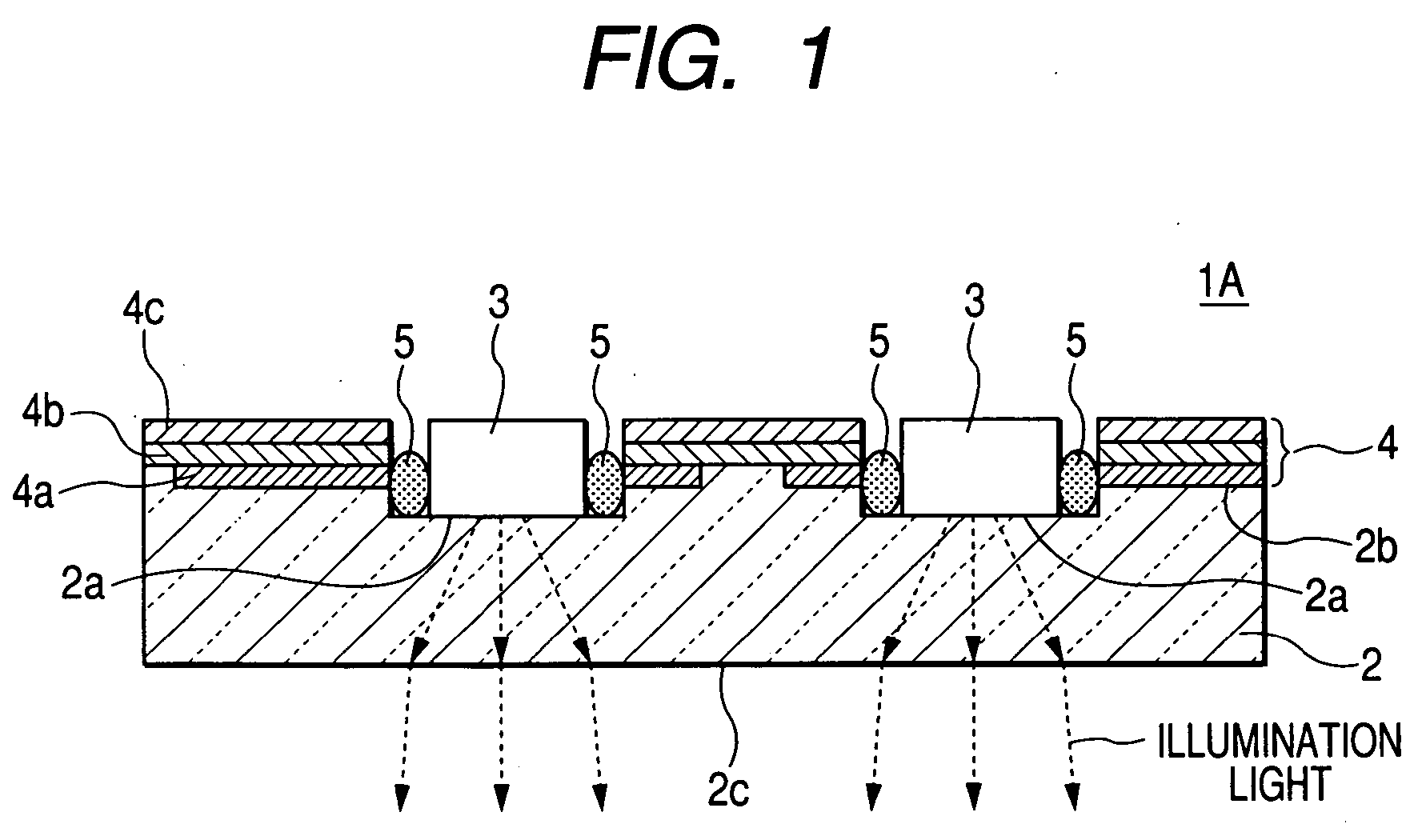
[0057] The wiring member 4 is formed over a portion from a receiving-portion-forming surface 2b of the lens 2 to a portion of a convex surface (lens surface) adjacent thereto. Also, the conductive portion 4a of the wiring member 4 is formed of a transparent conductive material such as indium-tin-oxide (ITO). Since the other portions are similar to those of the second embodiment, corresponding portions are denoted by the same reference numerals and thus, their description will be omitted.

[0058] The reflecting film 31 is formed on the convex surface of the lens 2 except for the forming portion of the wiring member 4. The reflecting film 31 may be formed by molding the lens 2 and then sputtering or vacuum-depositing a material having a high reflectivity such as aluminum.

[0059] The lens housing 32 is formed of a metal material or a plastic material in a tube shape having a predetermined shape and size to maintain the lens 2, and one end thereof is adhered to the surface of the printed ...

fourth embodiment

[0063] Since, in the illuminating device 1D the switch 33 is manipulated by pressing the lens 2, a special member for manipulating the switch 33 can be omitted and thus small-size and low manufacturing cost of the illuminating device can be accomplished.

[0064] Further, although, in the illuminating device 1D according to the fourth embodiment, the flexible circuit board 35 is included in a connecting unit for electrically connecting the conductive portion 4a of the wiring member 4 with the conductive portion 34a of the printed circuit board 34, a brush 41 of which one end is electrically connected with the conductive portion 34a of the printed circuit board 34 may be included as the connecting unit, and the front end of the brush 41 may elastically contact the conductive portion 4a of the wiring member 4, as shown in FIG. 7.


PUM


Abstract

The illuminating device includes a lens formed of a resin mold and having a portion for receiving an LED which is formed on one surface thereof, the LED received in the receiving portion, and a wiring member deposited on the receiving-portion-forming surface of the lens, and light irradiated from the LED is incident to the lens. In the method of fabricating the illuminating device, a transfer film having a conductive portion is set in a lens molding cavity and a wiring member including a conductive portion is deposited on one surface of the lens while the lens is injected and molded.

Description

BACKGROUND OF THE INVENTION [0001] 1. Field of the Invention [0002] The present invention relates to an illuminating device suitable for a room lamp for a vehicle and a method of fabricating the same, and more particularly, to a construction of an illuminating device using a light emitting diode (hereinafter, referred to as “LED”) as a light source and a method of fabricating the same. [0003] 2. Description of the Related Art [0004] Conventionally, a map lamp or a room lamp for a vehicle includes a small-sized valve lamp (a miniature bulb) as a light source. [0005]FIG. 8 is a cross-sectional view of an illuminating device known in the prior art. As can be apparently seen from FIG. 8, the illuminating device of the present example includes a circuit board 104 on which a socket 101 of a valve lamp, a required chip component 102 such as a resistor and an external connector 103 are mounted, a valve lamp 105 attached to the socket 101, a case 106 which also functions as a reflection plat...

Claims


Application Information

Patent Timeline
Patent Type & Authority Applications(United States)
IPC IPC(8): H01L31/112B60Q3/02F21W106/00H01H13/02
CPCB60Q3/0279B60Q3/0286B60Q3/0296F21K9/00H01L25/0753H01L33/486H01L33/60H01L2224/16B60Q3/74B60Q3/76B60Q3/82
Inventor TAKAHASHI, HIDEYUKIMIYAZAWA, SATOSHIHAYAMA, TSUYOSHINAKANO, AKIRAUCHIDA, RYOSUKE
Owner ALPS ALPINE CO LTD
Why Eureka
Try Eureka