Position and electromagnetic field sensor

a sensor and electromagnetic field technology, applied in the field of position and electromagnetic field sensors, can solve the problems of sensor not necessarily allowing monitoring of moving objects, electromagnetic energy loss variation within the oscillator, etc., and achieve the effect of increasing spatial resolution and insensitive to amplitude nois

Inactive Publication Date: 2006-05-11
ISIS INNOVATION LTD
View PDF18 Cites 4 Cited by
  • Summary
  • Abstract
  • Description
  • Claims
  • Application Information

AI Technical Summary

Benefits of technology

[0010] The oscillator is preferably a self-oscillating, closed loop oscillator, such as a Robinson marginal oscillator, a Van der Pol marginal oscillator or any oscillator variant with intermediate characteristics. In the case of the Robinson marginal oscillator in particular, it is preferable that an oscillator loop and limiter detector is employed. This potentially allows ope...

Problems solved by technology

In use, the sensor electromagnetic field is presented with a change in electric or magnetic susceptibility, which may cause a variation in electromagnetic energy losses within the oscillator.
Although there are particular advantages associated with a composite sensor having...

Method used


Image

  • Position and electromagnetic field sensor
  • Position and electromagnetic field sensor
  • Position and electromagnetic field sensor

Examples


Embodiment Construction

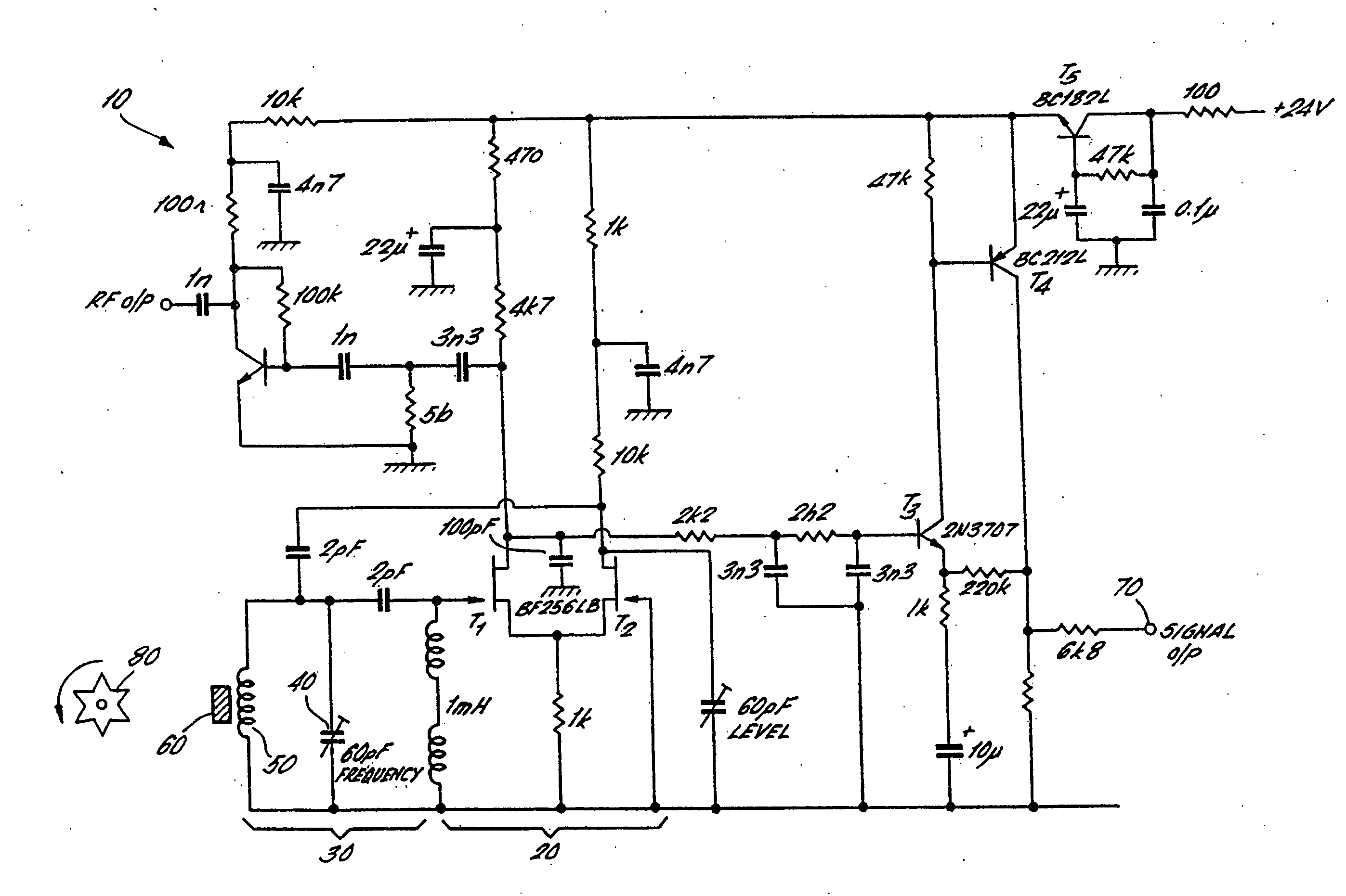
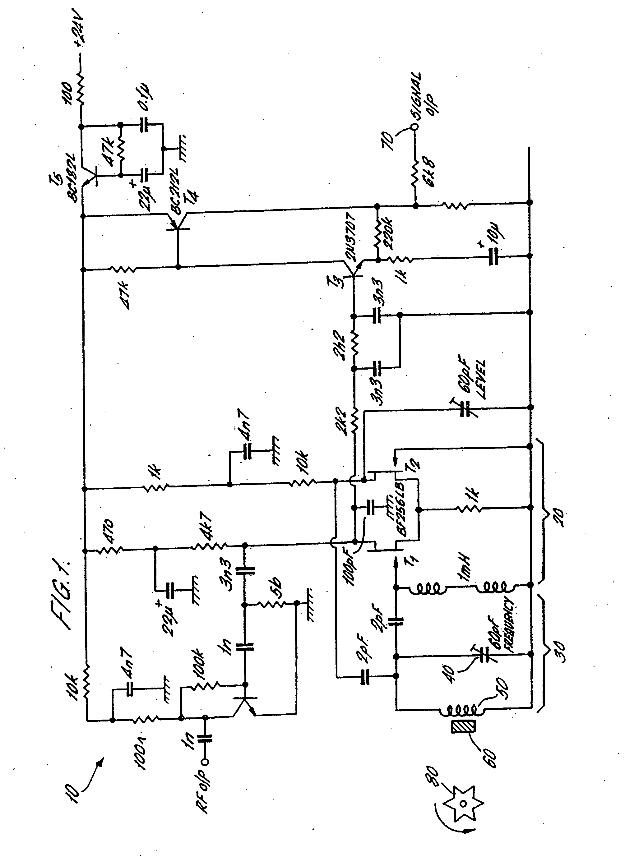
[0032]FIG. 1 shows a circuit diagram of a sensor according to a first embodiment of the invention. The circuit 10 comprises a closed loop Robinson-type oscillator 20 connected with a tank circuit 30. The tank circuit 30 comprises a capacitor and inductor provided by a variable capacitor 40 in parallel with a coil 50. The coil 50 is wrapped around a sensor element 60 and comprises a piece of colossal magnetoresistive material such as lanthanum strontium manganite (LSMO). This material has a strong variation in the imaginary part of its susceptibility, as a magnetic field applied to it varies.

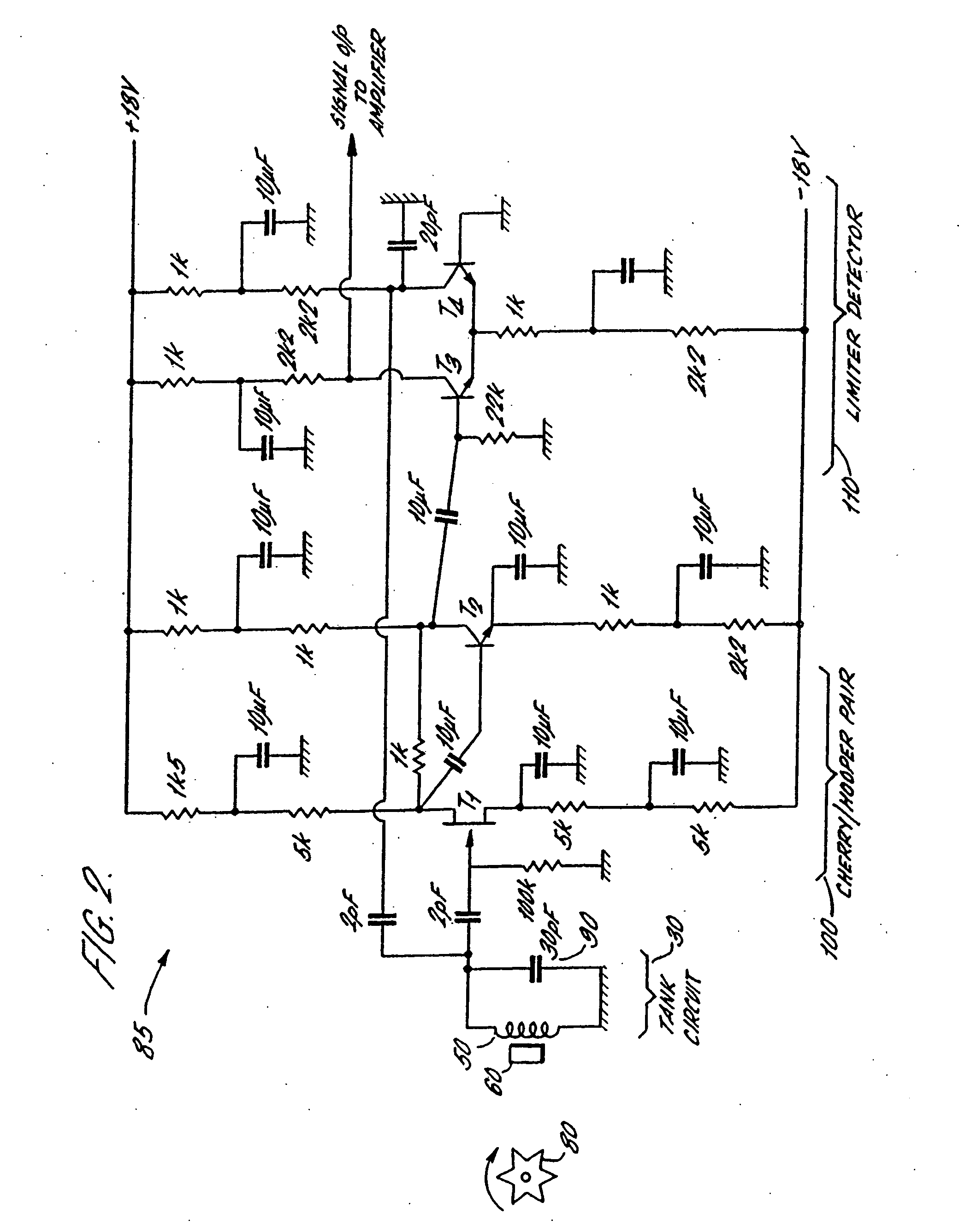
[0033] In the circuit of FIG. 1, transistors T1 and T2 have a triple function. Firstly, they provide the gain to keep the closed loop Robinson oscillator 20 running, secondly they provide a limiting action which makes the feedback independent of amplitude noise, and thirdly they perform detection to generate an output signal. These three functions provided by transistors T1 and T2 may be separat...


PUM


Abstract

A position and electromagnetic field sensor is provided. The sensor relies upon an oscillator such as a Robinson marginal oscillator to generate an rf or microwave electromagnetic field. As an inhomogeneously-shaped object, such as a metallic toothed wheel, for example, moves through the resultant field, the field experiences a change in electric or magnetic susceptibility. This in turn causes energy losses in the oscillator the magnitude of which can be output as a d.c. signal related thereto. To detect non-moving objects which nevertheless generate an electromagnetic field or have attached to them a source thereof, the sensor may also include a giant or colossal magnetoresistive structure located adjacent the oscillator coil, the structure having an imaginary magnetic susceptibility which is strongly dependent upon the magnitude and direction of the field generated by or at the object to be sensed.

Description

RELATED APPLICATIONS [0001] This application is a divisional application of application Ser. No. 10 / 211,543, filed Jan. 16, 2003, which is a National Stage of International Application PCT / GB01 / 01085, filed Mar. 13, 2001. Application Ser. No. 10 / 211,543 is hereby incorporated by reference in its entirety.BACKGROUND OF INVENTION [0002] This application relates to a sensor for detecting the position of an object and / or an electromagnetic field associated with that object. SUMMARY [0003] In embodiments of a first aspect of the present invention, there are provided a susceptibility sensor for detecting relative movement between an inhomogeneously-shaped object to be sensed and the sensor, comprising: an oscillator including a sensor electromagnetic field generator; and an output arranged to provide a signal which varies in dependence upon the change in the electrical properties of the said oscillator; the sensor being arranged such that relative movement between the object to be sensed ...

Claims


Application Information

Patent Timeline
IPC IPC(8): G01R27/28G01D5/245G01V3/10
CPCG01D5/2013G01V3/101G01D5/202
Inventor GREGG, JOHN FRANCIS
Owner ISIS INNOVATION LTD
Why Eureka
Try Eureka