LUT based multiplexers

a multiplexer and lut technology, applied in the field of improved lut based multiplexer architecture, can solve the problems of increasing the logic depth of the multiplexer, increasing the delay, and requiring a large number of luts, and achieve the effect of less constrain

Inactive Publication Date: 2006-05-11
STMICROELECTRONICS PVT LTD
View PDF13 Cites 7 Cited by
  • Summary
  • Abstract
  • Description
  • Claims
  • Application Information

AI Technical Summary

Benefits of technology

[0024] It is an additional object of the invention to provide a flexible multiplexer implementation using logic chains (carry-cascade)

Problems solved by technology

The drawback of this invention is that it increases the logic depth of the multiplexer logic thereby increasing the delay.
However this architecture requires a large number of LUTs for implementing a multiplexer.
A major disadvantage of this architecture

Method used


Image

  • LUT based multiplexers
  • LUT based multiplexers
  • LUT based multiplexers

Examples


Embodiment Construction

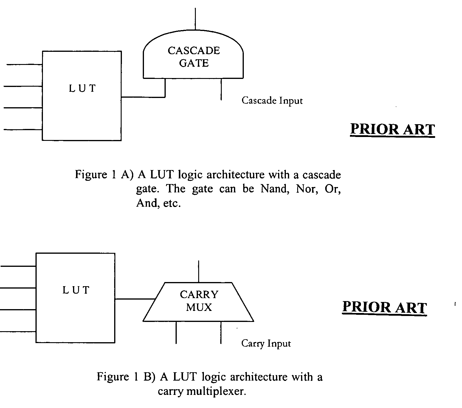
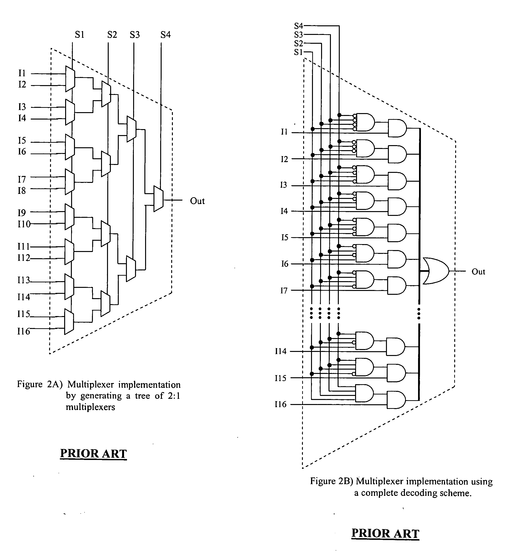
[0058] The FIGS. 1A, 1B, 2A, 2B, 2C, 2D, 2E, have already been described in detail above under the heading “BACKGROUND OF THE INVENTION”.

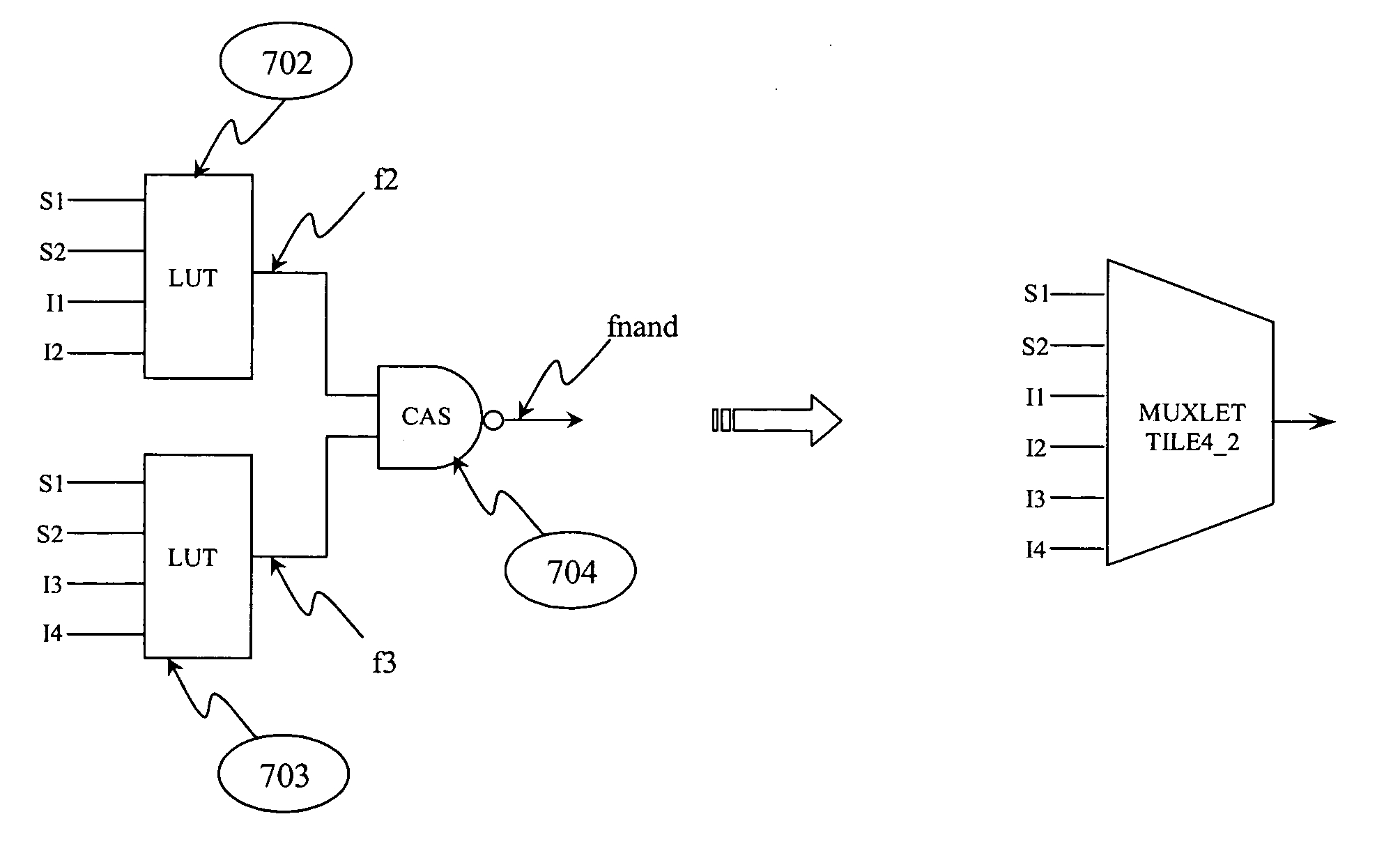
[0059] According to an embodiment of the present invention a multiplexer is implemented in a number of stages where each stage is of size R and is termed as a muxlet. The first stage (first muxlet) of the multiplexer takes as input some select lines of the multiplexer and all data inputs. A muxlet performs partial multiplexing by producing output data lines that are multiplexed from the input data lines that are greater in number by a factor of 2ˆR. The multiplexing is based on the value (signal value) of R input select lines. The resultant output is used as data input for the next stage. Many such stages (muxlets) form a tree structure to implement the multiplexer. Thus each muxlet decodes the input data lines based on the value of some select lines and many such muxlets form a tree structure to implement the multiplexer.

[0060]FIGS. 3A to 3C ill...


PUM


Abstract

An improved LUT based multiplexer, including a first set of muxlets, each receiving a subset of input data lines at its inputs and one or more muxlet stages cascaded together to form a tree structure in which the roots are the first set of muxlets and the last stage of muxlet produces the final output.

Description

CROSS-REFERENCE TO RELATED APPLICATION [0001] This application is based upon and claims priority from prior Indian Patent Application No. 1817 / Del / 2004, filed on Sep. 24, 2004, the entire disclosure of which is herein incorporated by reference. BACKGROUND OF THE INVENTION [0002] 1. Field of the Invention [0003] The invention relates to an improved LUT based multiplexer architecture. More particularly, the invention relates to a method and apparatus for implementing multiplexers in Field Programmable gate arrays (FPGA) and other programmable devices that have a Lookup Table (LUT) based logic architecture. [0004] 2. Description of the Related Art [0005] A multiplexer is a basic digital electronics component composed of n select lines and at most 2n data lines. The multiplexer selects one of its inputs and provides it at its output according to the state of the select line / s. Multiplexers are typically used in digital Integrated Circuit (IC) designs by either direct use through schemat...

Claims


Application Information

Patent Timeline
IPC IPC(8): H03K19/177
CPCH03K19/17728
Inventor BHATTI, NARESH KUMARSINGHAL, SONIA
Owner STMICROELECTRONICS PVT LTD
Why Eureka
Try Eureka