
Image processing apparatus and method of controlling an image processing apparatus

Inactive Publication Date: 2006-05-11
CANON KK
View PDF11 Cites 36 Cited by
  • Summary
  • Abstract
  • Description
  • Claims
  • Application Information

AI Technical Summary

Benefits of technology

[0012] In view of the above, the present invention provides an improved image proce

Problems solved by technology

However, in the copying machine disclosed in Japanese Unexamined Patent Application Publication No. 2002-8002, it is impossible to perform in parallel the same image process on a plurality of divided image data, although it is possible to perform in parallel different image processes on a plurality of divided image data.
For example, in this technique, although it is possible to perform in parallel a color conversion on divided image data and a resolution conversion on another divided image data by operating corresponding modules at the same time, it is impossible to perform in parallel a color conversion on a plurality of divided image data, because there is only one module for the color conversion.
However, in the copying machine disclosed in Japanese Unexamined Patent Application Publication No. 2002-8002, it is impossible to perform in parallel an image process on divided image data generated from one page of original image data, and thus it takes a long time to perform the image process.
However, the result is an increase in the circuit complexity and a corresponding increase in cost, and thus this technique is not a good solution.

Method used


Image

  • Image processing apparatus and method of controlling an image processing apparatus
  • Image processing apparatus and method of controlling an image processing apparatus
  • Image processing apparatus and method of controlling an image processing apparatus

Examples


first exemplary embodiment

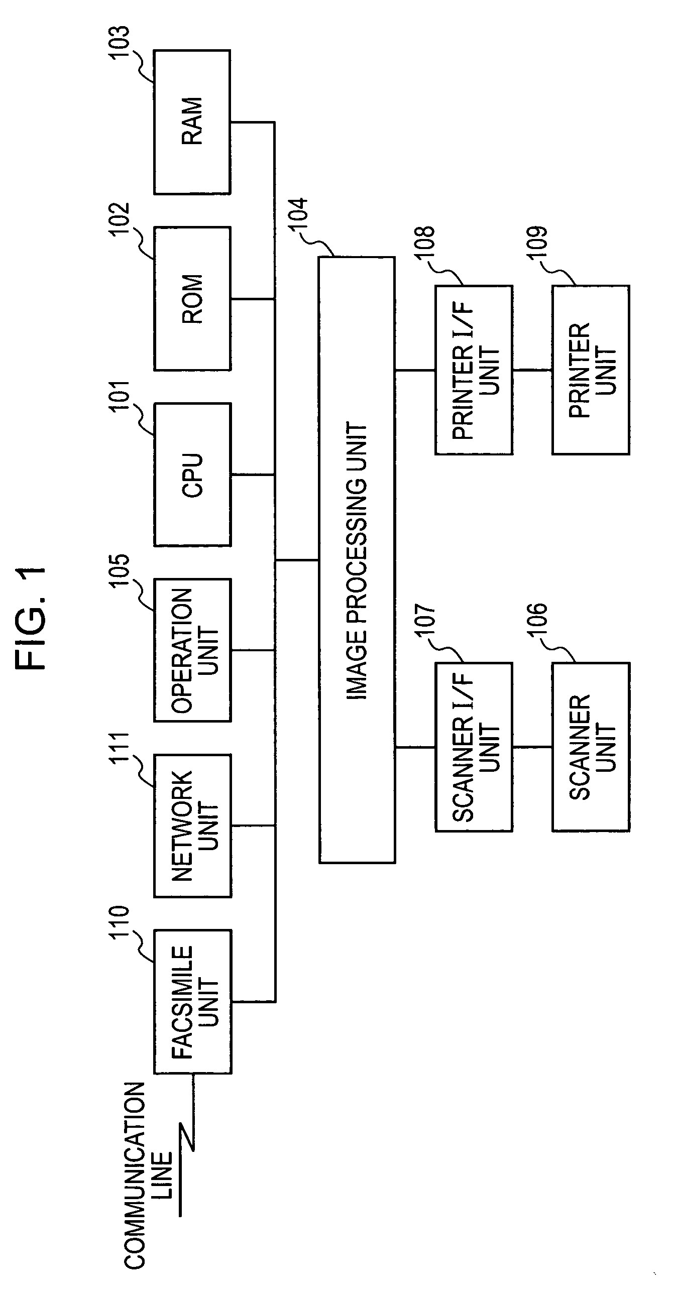
[0043]FIG. 1 is a block diagram illustrating an exemplary MFP (Multi Function Peripheral) serving as an image processing apparatus. Although in the embodiments described below, it is assumed that the MFP has a plurality of functions such as a facsimile function, a printing function, a copying function, etc. and is capable of dealing with color image data, the MFP may be capable of dealing with only monochrome image data.

[0044] First, the general architecture of the MFP according to the present embodiment is described with reference to a block diagram shown in FIG. 1. A CPU 101 controls the operation of the MFP including various parts such as an image input / output apparatus including a scanner unit and a printer unit, an image processing unit, and a communication unit. The CPU 101 also performs a process of generating packet data described later. An operation program for controlling the operation of the MFP is stored in a ROM 102. A RAM 103 is used as a work area in the operation of...

example 1

[0108] When the management table is in such a state as denoted by reference numeral 1900 in FIG. 17A, if packet data having such a header as denoted by reference numeral 800 in FIG. 8A is input from the input I / F unit on the side of the system bus 1701, a process is performed as follows.

[0109] First, when packet data is received in step S901, a determination is made in step S902 as to whether an IP function is needed. In this specific case, IP2 is specified in the first part of the first header of the packet, and thus it is determined in step S902 that an IP function corresponding to IP2 is needed. Thus, the packet data is transferred to the header converter 1703 (see FIG. 15).

[0110] Thereafter, in step S904, the reconfigurable circuit unit searching process is performed in a similar manner as described above. In step S909 in the reconfigurable circuit unit searching process described above with reference to FIG. 9B, it is determined from the first part of the header that a resolu...

example 2

[0117] When the management table is in such a state 2000 shown in FIG. 18, if packet data with a header in a state 1100 shown in FIG. 11 is input from the input I / F unit on the side of the system bus 1701 (see FIG. 15), the exemplary process which will be described next is performed. Note that the process is also performed under the control of the controller 1702 as in Example 1 described above.

[0118] First, when packet data is received in step S901 (see FIG. 9A), it is determined in step S902 that IP functions are needed, because IP2, IP3, and IP4 are specified in the first parts of the respective first, second, and third headers. Thus, the packet data is transferred to the header converter 1703 (see FIG. 15).

[0119] Thereafter, in step S904 (see FIG. 9A), the reconfigurable circuit unit searching process is performed. In step S909, from the first parts of the respective headers, it is determined that three IP functions, that is, the resolution conversion (IP2), the binarization (...


PUM


Abstract

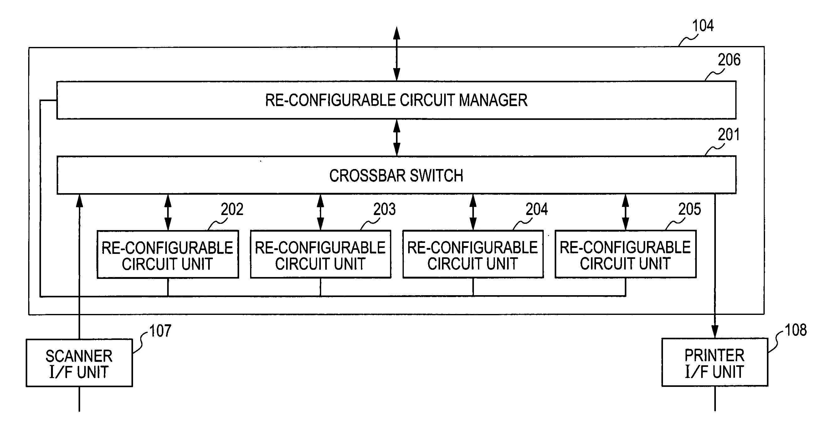
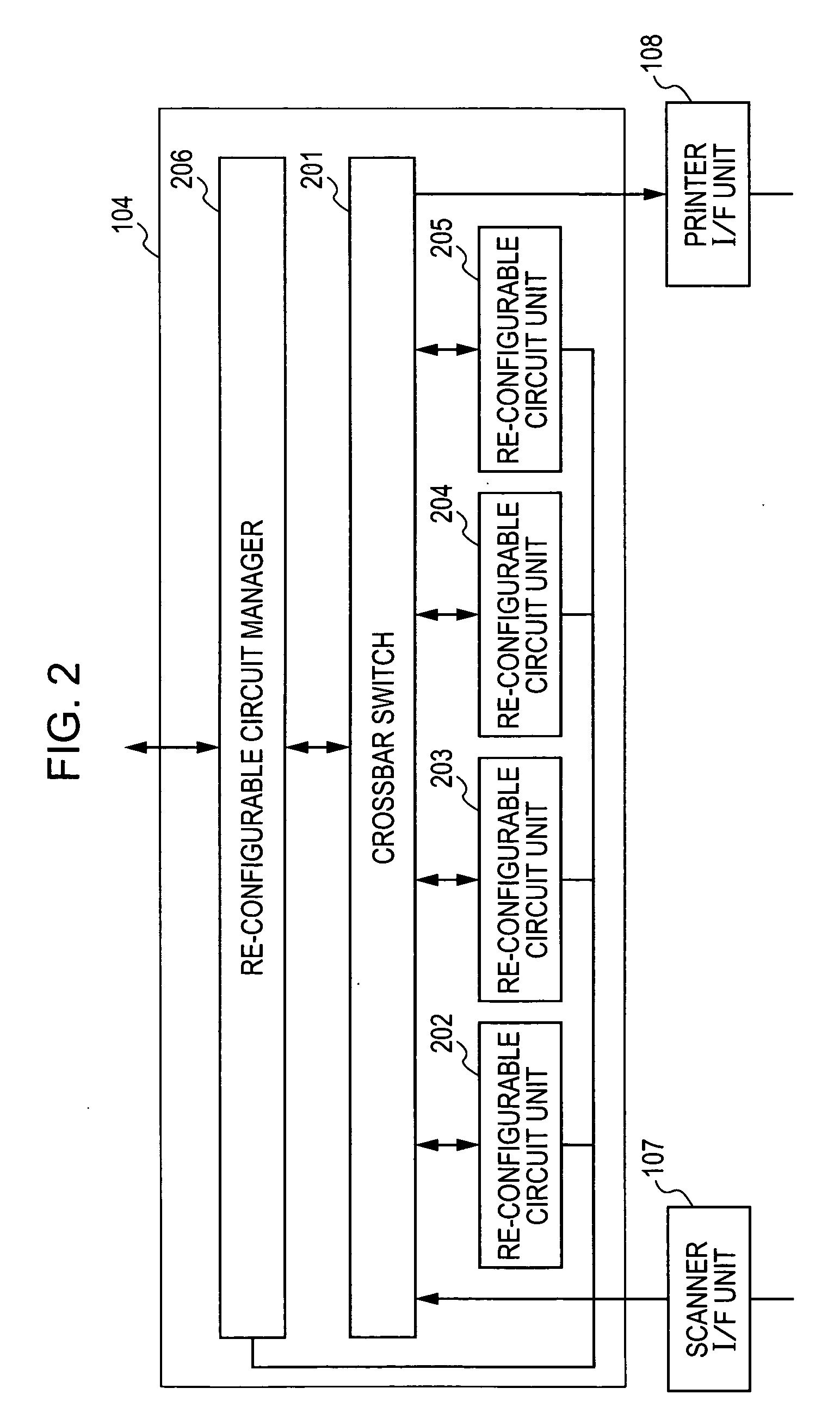
An image processing apparatus capable of performing a plurality of types of image processes on image data includes a dividing unit adapted to divide input image data into area images, a data generation unit adapted to generate data including an area image and type information indicating a type of an image process to be performed, an image processing unit including a plurality of image processing sub-units each capable of being reconfigured so as to function as a circuit capable of performing selected one of the plurality of types of image processes, a commanding unit adapted to command at least one of the plurality of image processing sub-units to be reconfigured so as to function as a circuit for performing an image process specified by the type information, and a transfer control unit adapted to transfer the area image to the image processing sub-unit specified by the commanding unit.

Description

BACKGROUND OF THE INVENTION [0001] 1. Field of the Invention [0002] The present invention relates to an image processing apparatus and a method of controlling an image processing apparatus. [0003] 2. Description of the Related Art [0004] Digital multi-function peripherals (MFPs) having multiple functions such as a copying function, a facsimile function, etc. are widely used. In the MFP, an input / output operation of a scanner unit or a printer unit, a process of making a connection to a network or a communication line, image processing on image data, and a combination of two or more of the operations described above are controlled by a controller (CPU) responsible for controlling the entire system. [0005] The MFP usually includes an image processing unit capable of performing a plurality of image processing such as a resolution conversion, binarization, rotation, color conversion, etc. on input image data. Various techniques in terms of parallel processing of two or more image proces...

Claims


Application Information

Patent Timeline
IPC IPC(8): H04N1/60G06F15/00
CPCG06T1/20
Inventor MATSUNAGA, DAISUKENAKAJIMA, YASUKI
Owner CANON KK
Learn More