
Frame transmitting apparatus and frame receiving apparatus

a frame transmitting apparatus and frame technology, applied in the direction of electrical equipment, digital transmission, error prevention, etc., can solve the problems of increased transmission error of data, increased cost, and difficulty in solving errors

Inactive Publication Date: 2006-05-11
FUJITSU LTD
View PDF3 Cites 49 Cited by
  • Summary
  • Abstract
  • Description
  • Claims
  • Application Information

AI Technical Summary

Benefits of technology

[0013] A frame transmitting apparatus according to one aspect of the present invention, which transmits a frame including data to be transmitted or a frame including control data for a data-transmission control via a network, includes a frame generating unit that generates a frame including identification-information-added data to which 1-bit identification information indicating whether a block obtained by dividing data into every n bits includes the control data is added, where n is a positive integer, and an error control code for a data-transmission error control; and a frame transmitting unit that transmits the frame generated.
[0014] A frame receiving apparatus according to another aspect of the present invention, which receives a frame including data to be transmitted or a frame including control data for a data-transmission control, includes a frame receiving unit that receives a frame including identification-information-added data to which 1-bit identification information indicating whether a block obtained by dividing data into every n bits includes the control data is added, where n is a positive integer, and an error control code for a data-transmission error control; a transmission-error control unit that executes a data-transmission error control based on the error control code included in the frame received; and a format converting unit that performs, when the data-transmission error control has been executed, a conversion of a frame format based on the identification information.
[0015] A frame transmitting apparatus according to still another aspect of the present invention, which transmits a frame including data to be transmitted or a frame including control data for a data-transmission control via a network, includes a frame generating unit that generates a frame by storing, when a block obtained by dividing data into every n bits includes the control data, where n is a positive integer, a block that includes the control data or a block from which the control data has been removed in a payload area of a digital-wrapper-format frame including an error control code, and storing information relating to the control data in a predetermined area of an overhead of the digital wrapper format; and a frame transmitting unit that transmits the frame generated.
[0016] A frame receiving apparatus according to still another aspect of the present invention, which receives a frame including data to be transmitted or a frame including control data for a data-transmission control, includes a frame receiving unit that receives a frame generated by storing, when a block obtained by dividing data into every n bit

Problems solved by technology

Now, when a 2-bit header is added, it is necessary to further increase a processing rate of a device for performing data transmission, which results in increase in cost.
In the conventional technique disclosed in Japanese Patent Application Laid-Open Publication No. 2002-271308, however, there is a problem that, when transmission error of data occurs, it is difficult to solve the error.
Specifically, when data is transmitted via an optical fiber according to a wavelength-division-multiplexing (WDM) system, a possibility that transmission error of data occurs is increased due to a non-linear optical effect that an optical fiber has such as self phase modulation (SPM) or cross phase modulation (XPM), where there is a problem that it is difficult to detect such transmission error.
As the conventional technique such as disclosed in the Patent Literature 1, however, when the 2-bit header is replaced by a 1-bit control bit, it becomes very difficult to control transmission error.
Therefore, it becomes important to solve a problem about how to control transmission error of data efficiently and how to suppress a processing rate required for a device for performing data transmission are serious problems.

Method used


Image

  • Frame transmitting apparatus and frame receiving apparatus
  • Frame transmitting apparatus and frame receiving apparatus
  • Frame transmitting apparatus and frame receiving apparatus

Examples


first embodiment

[0047]FIG. 3 is a diagram of a configuration of the frame transmitting system according to the present invention. As shown in FIG. 3, the frame transmitting system is constituted of terminal devices 50a to 50h, routers 60a to 60d, transponders 70a to 70d, and WDM devices 80a and 80b.

[0048] Each of the terminal devices 50a to 50h is a device that performs transmission and reception of data with another terminal device. Specifically, when each of the terminal devices 50a to 50h transmits an IP packet to another terminal device, it generates an MAC frame storing the IP packet therein to a corresponding one of the routers 60a to 60d. Each of the terminal devices 50a to 50h receives an MAC frame from a corresponding one of the routers 60a to 60d to perform a processing for taking an IP packet from the MAC frame.

[0049] Each of the routers 60a to 60d is a router that selects a proper path through which the MAC frame should be transferred based on address information of a transmission des...

second embodiment

[0092]FIG. 7 is a block diagram of a functional configuration of a router according to the Detailed explanation about functional units having the same functions as those in the transponder 70a shown in FIG. 4 will be omitted.

[0093] As shown in FIG. 7, the router 90 includes a MAC frame receiving unit 901, a MAC frame termination processing unit 902, a routing processing unit 903, a storage unit 904, a 1-bit overhead frame generating unit 905, a digital wrapper frame generating unit 906, an electric-optical signal converting unit 907, a digital wrapper frame transmitting unit 908, a digital wrapper frame receiving unit 909, an optical-electric signal converting unit 910, a digital wrapper frame termination processing unit 911, a 1-bit overhead frame termination processing unit 912, and a MAC frame transmitting unit 913.

[0094] The MAC frame receiving unit 901 receives an electric signal of a MAC frame transmitted from a terminal device. The MAC frame termination processing unit 902 ...

third embodiment

[0123] such a constitution is employed that the digital wrapper frame is transmitted via the two network lines 300a and 300b in parallel, but this invention is not limited to this constitution. The digital wrapper frame may be transmitted via three or more network lines in parallel.

[0124] The LAN-PHY / digital wrapper frame converting unit 1002 outputs digital wrapper frame storing multi-frame number information stored in the OH to the digital wrapper frame transmitting units 1003a and 1003b.

[0125] The digital wrapper frame transmitting units 1003a and 1003b perform processings for transmitting digital wrapper frame generated by the LAN-PHY / digital wrapper frame converting unit 1002 via different network lines 300a and 300b, respectively.

[0126] The uninterruptible LAN-PHY device 200 includes digital wrapper frame receiving units 2001a and 2001b, optical-electric signal converting units 2002a and 2002b, digital wrapper frame termination processing units 2003a and 2003b, 1-bit overhe...


PUM


Abstract

A frame transmitting apparatus that transmits a frame including data to be transmitted or a frame including control data for a data-transmission control via a network includes a frame generating unit that generates a frame including identification-information-added data to which 1-bit identification information indicating whether a block obtained by dividing data into every n bits includes the control data is added, where n is a positive integer, and an error control code for a data-transmission error control; and a frame transmitting unit that transmits the frame generated.

Description

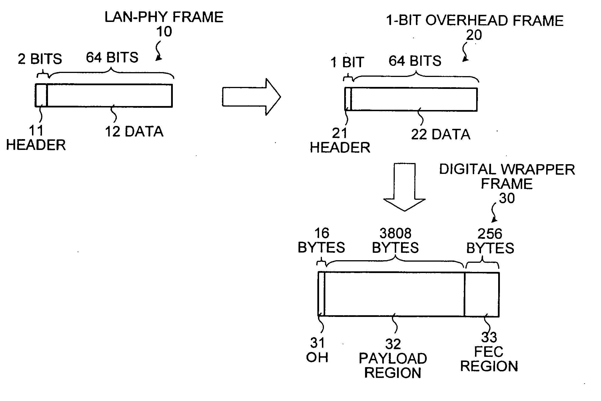
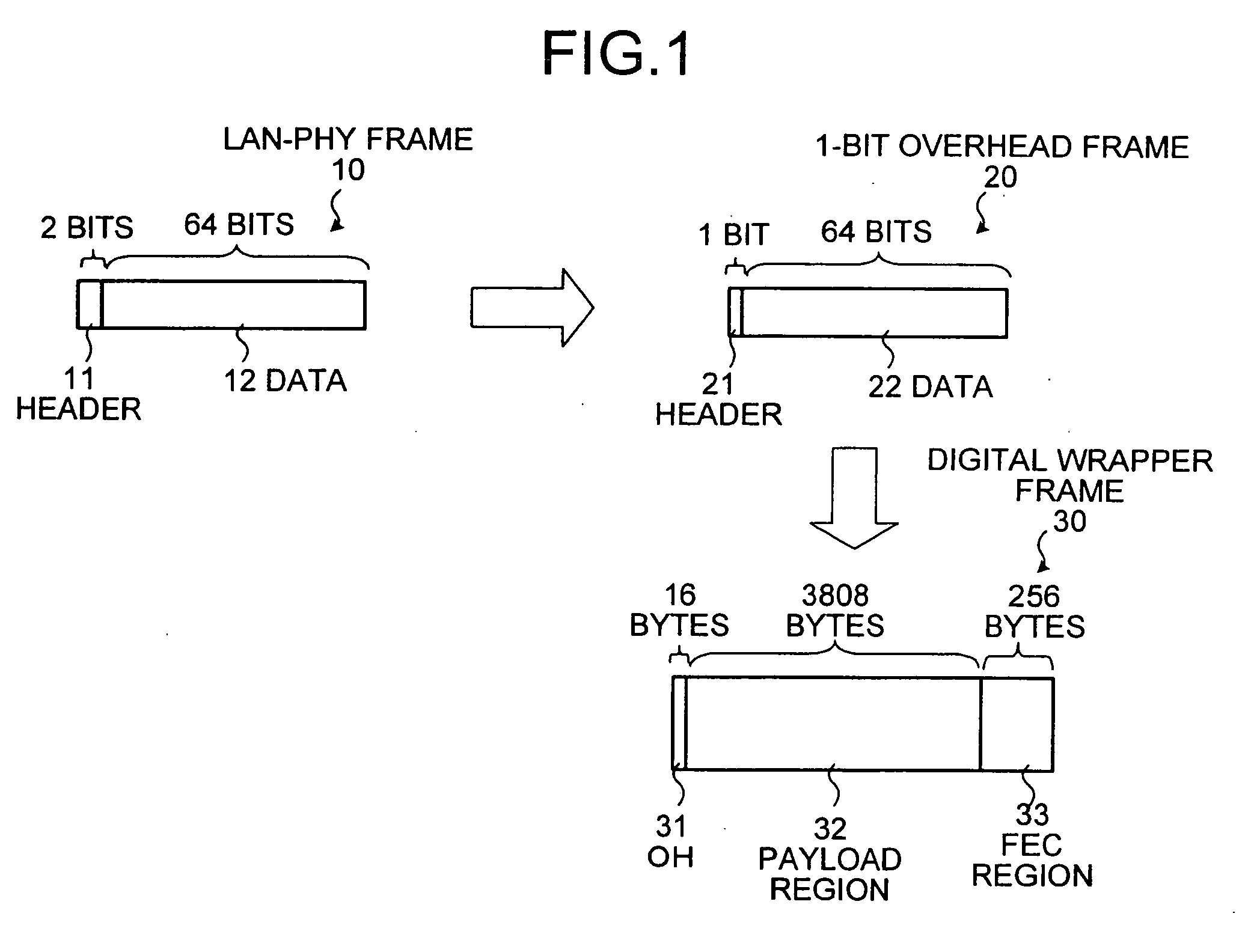
BACKGROUND OF THE INVENTION [0001] 1) Field of the Invention [0002] The present invention relates to a technology for controlling a transmission error of data, reducing a transmission band required for transmitting data, and suppressing a processing speed required for an apparatus that performs a data transmission, when transmitting and receiving a frame including data to be transmitted or a frame including control data for a transmission control. [0003] 2) Description of the Related Art [0004] Conventionally, a frame format called “LAN-PHY” is defined in a standard of 10 Gigabit Ethernet (registered trademark). Specifically, the frame format of LAN-PHY is a frame format obtained by adding a 2-bit header to each 64 bits in a MAC frame and performing conversion to a 66-bit block. A processing for the conversion is generally called “64B / 66B coding”. [0005] When data is included alone in the LAN-PHY frame, a value of the 2-bit header is set to “01”. When control code is included in the...

Claims


Application Information

Patent Timeline
IPC IPC(8): H04J3/16
CPCH04J3/0602H04J3/1658H04J2203/006H04L1/0041H04L1/0057H04L25/4908
Inventor TAKAKUWA, MAKOTOIZUMI, FUTOSHIYOSHIMOTO, MASAHIROHOSOKAWA, TAKAHIRO
Owner FUJITSU LTD
Learn More