
Continuous phase modulation system and method with added phase pulse

a phase pulse and continuous phase technology, applied in the field of communication systems, can solve the problems of non-constant amplitude, low and complex demodulation of receivers, and achieve the effects of increasing throughput or power efficiency, constant amplitude, and increasing the data rate of continuous phase modulated waveforms

Inactive Publication Date: 2006-05-11
HARRIS CORP
View PDF8 Cites 10 Cited by
  • Summary
  • Abstract
  • Description
  • Claims
  • Application Information

AI Technical Summary

Benefits of technology

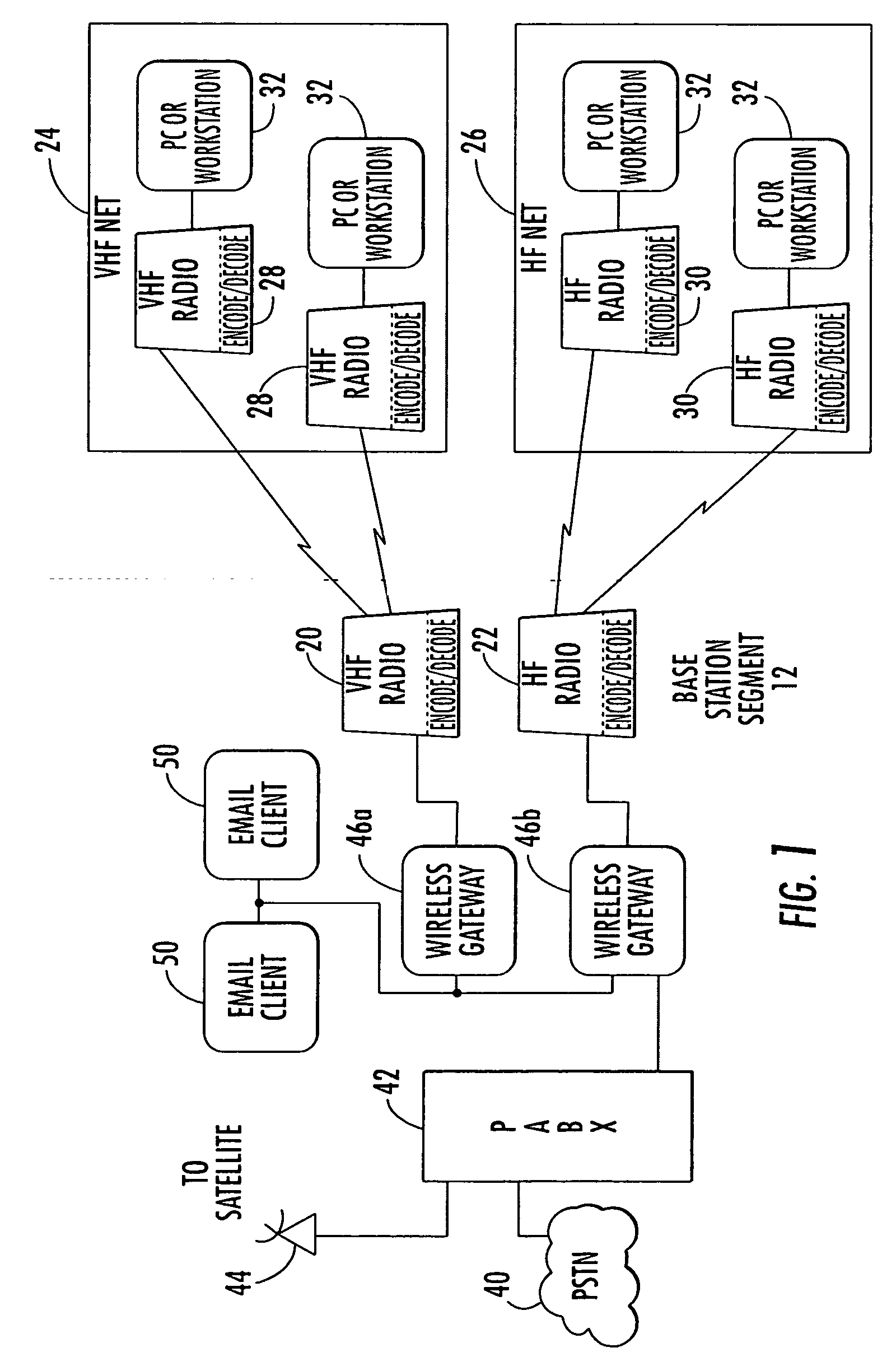
[0008] The present invention provides a new constant-amplitude, higher-throughput and lower complexity, continuous phase modulated waveform. The data rate of the continuous phase modulated waveform is increased without incurring a higher complexity coding scheme. The system and method of the present invention provides for the selection of bandwidth and data rate to achieve increased throughput or power efficiency. This solves the desire by some for a waveform that has constant amplitude and is bandwidth and / or power efficient without significantly increasing complexity.
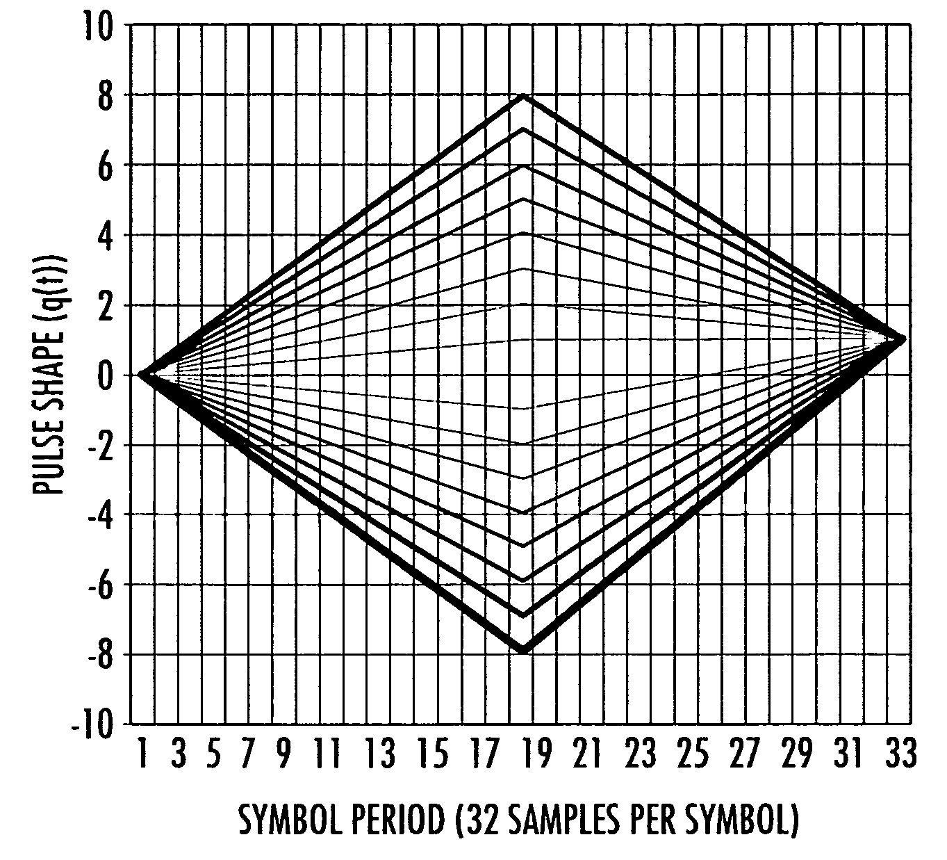
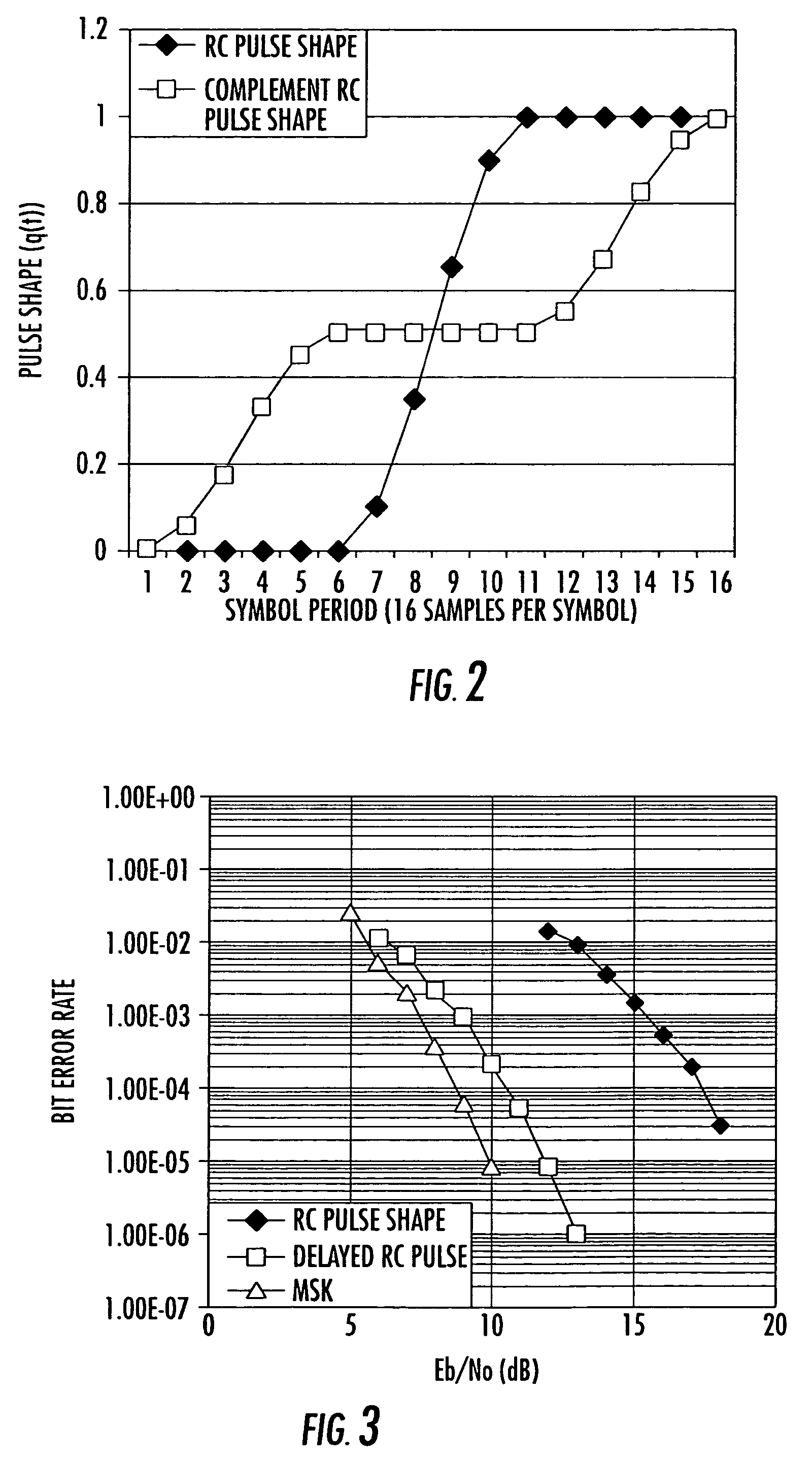
[0011] In yet another aspect of the present invention, the phase pulse shape is varied to increase the number of bits per transmitted symbol (instead of traditional approach of increasing the symbol alphabet of underlying trellis modulation increasing trellis complexity). An example of system increase from a binary (i.e., 2-ary) symbol to a 4-ary symbol by modifying a first pulse to change from 0 to 1 at the start of a symbol and change the second pulse from 0 to 1 at the end of the signal. This is just an example of two different phase pulses, but many different pulse shapes exist. In order to improve performance, the system can generate a phase pulse that has a shape that increases the correlation metric difference a Euclidean distance spaced apart greater than the square root of two. In addition, the peak point of a pulse can be moved to another sample point on the symbol.

Problems solved by technology

Some limitations of these schemes are receiver demodulation complexity and non-constant amplitude.
Thus, the receiver complexity is not greatly increased.

Method used


Image

  • Continuous phase modulation system and method with added phase pulse
  • Continuous phase modulation system and method with added phase pulse
  • Continuous phase modulation system and method with added phase pulse

Examples


Embodiment Construction

[0029] The present invention will now be described more fully hereinafter with reference to the accompanying drawings, in which preferred embodiments of the invention are shown. This invention may, however, be embodied in many different forms and should not be construed as limited to the embodiments set forth herein. Rather, these embodiments are provided so that this disclosure will be thorough and complete, and will fully convey the scope of the invention to those skilled in the art. Like numbers refer to like elements throughout, and prime notation is used to indicate similar elements in alternative embodiments.

[0030] The present invention is applicable to communication systems and products in general and particularly systems that require modulation schemes that occupy a fixed bandwidth channel (LOS, cable or SATCOM) (fixed frequency spectrum). The present invention can take advantage of the memory (usually represented as a trellis structure) of a coded waveform (i.e., PSK, ASK,...


PUM


Abstract

A signal generator generates a coded or memory waveform having a trellis structure. A modulator is operative with the signal generator for adding at least one phase pulse to the trellis structure of the coded or memory waveform to create a substantially constant envelope modulated signal that increases the transmitted bits per symbol.

Description

FIELD OF THE INVENTION [0001] The present invention relates to the field of communications systems, and more particularly, the present invention relates to communications systems and related methods that use continuous phase modulation and similar modulation schemes. BACKGROUND OF THE INVENTION [0002] Some multi-band or other tactical radios operate in the high frequency (HF), very high frequency (VHF) (for satellite communications), and ultra high frequency (UHF) bands. The range of multi-band tactical radios can operate over about 2 through about 512 MHz frequency range. Next generation radios should cover about 2.0 to about 2,000 MHz (or higher) to accommodate high data rate waveforms and less crowded frequency bands. This high frequency transmit mode is governed by standards such as MIL-STD-188-141B. UHF standards, on the other hand, provide different challenges over the 225 to about 512 MHz frequency range, including short-haul line-of-sight (LOS) communication and satellite co...

Claims


Application Information

Patent Timeline
Patent Type & Authority Applications(United States)
IPC IPC(8): H04L23/02
CPCH04L25/03834H04L27/18H04L27/2017H04L27/3405
Inventor NORRIS, JAMES A.NIETO, JOHN W.
Owner HARRIS CORP
Learn More