Ultrasonic probe and ultrasonic diagnostic apparatus

a technology of ultrasonic probes and diagnostic equipment, applied in tomography, applications, instruments, etc., can solve the problems of difficult to maintain the surface temperature at its front end lower than a predetermined level, affecting the cooling efficiency of the object, and affecting the operation. , to achieve the effect of improving cooling efficiency and operation

Inactive Publication Date: 2006-05-11
TOSHIBA MEDICAL SYST CORP
View PDF5 Cites 39 Cited by
  • Summary
  • Abstract
  • Description
  • Claims
  • Application Information

AI Technical Summary

Benefits of technology

[0021] The present invention has been made in light of the conventional situations, and it is the first object of

Problems solved by technology

However, if the power of transmitting ultrasonic waves is increased, the heat value in the ultrasonic probe is also increased so as to largely increase the surface temperature of the probe, thereby giving the object discomfort.
Recently, an ultrasonic probe capable of three-dimensional scanning has been developed, which includes two-dimensionally arranged transducers so as to three-dimensionally apply ultrasonic waves, and it has begun limited practical operations.
Accordingly, in the ultrasonic probe capable of three-dimensional scanning, with increasing number of transducers and with increasing circuit scale, the heat value is increased, so that it is difficult to maintain the surface temperature at its front end lower than a predetermined level.
On the other hand, in the ultrasonic probe housing a number of transducers or a number of transducers and a circuit board, the temperature of not only the front end of a probe unit but also of the entire probe unit is increased, so that a safety problem in handling the probe unit arises for an operator of the ultrasonic probe who gets hold it directly with a hand.
Since the probe unit is provided with a endothirm part for absorbing the heat, the ultrasonic

Method used


Image

  • Ultrasonic probe and ultrasonic diagnostic apparatus
  • Ultrasonic probe and ultrasonic diagnostic apparatus
  • Ultrasonic probe and ultrasonic diagnostic apparatus

Examples


first embodiment

1. First Embodiment

[0065] An ultrasonic probe according to a first embodiment of the present invention will be described with reference to FIGS. 1 to 3 and by exemplifying a case where a refrigerant for cooling a heat-receiving part of the ultrasonic probe and a cooler for air-cooling the refrigerant are provided.

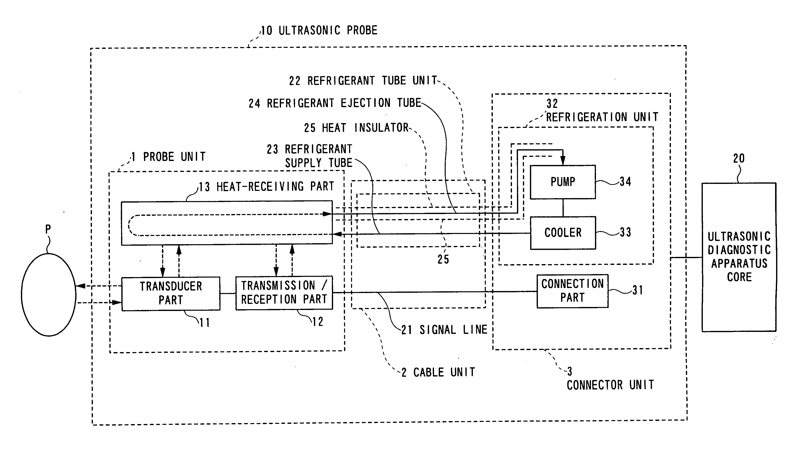
[0066]FIG. 1 is a block diagram showing an ultrasonic probe according to the first embodiment of the present invention.

[0067] An ultrasonic probe 10 includes a probe unit l, a cable unit 2 and a connector unit 3. The probe unit 1 transmits and receives ultrasonic waves to and from an object P. The cable unit 2 communicates signals for generating ultrasonic waves to the probe unit 1 and signals form the probe unit 1. The connector unit 3 which is detachable communicates signals for generating ultrasonic waves from an ultrasonic diagnostic apparatus core 20 to the cable unit 2 and signals from the cable unit 2 to the ultrasonic diagnostic apparatus core 20.

[0068] The probe...

second embodiment

2. Second Embodiment

[0095] An example of a cable unit of an ultrasonic probe according to a second embodiment of the present invention will be described below with reference to FIG. 4.

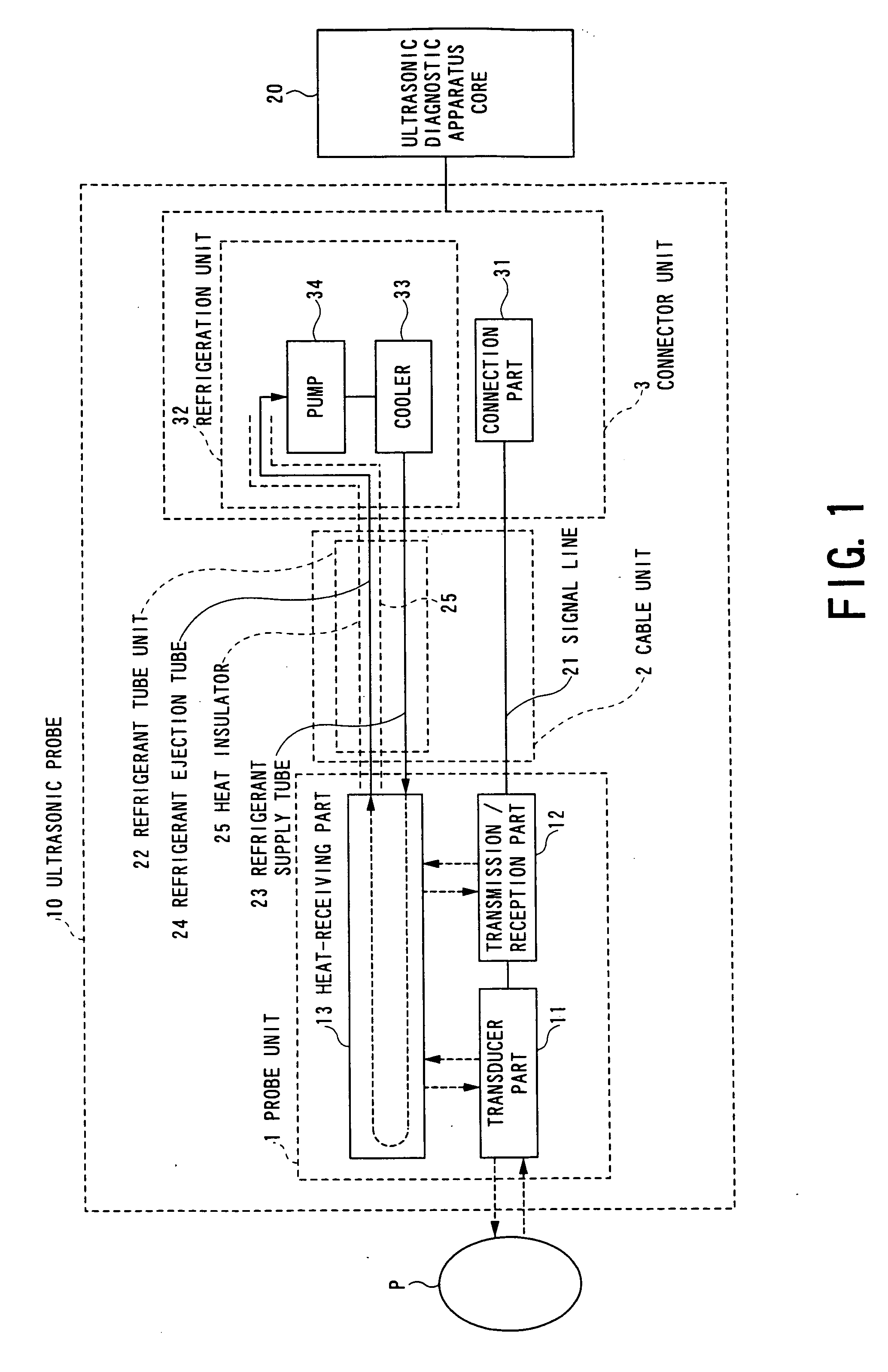
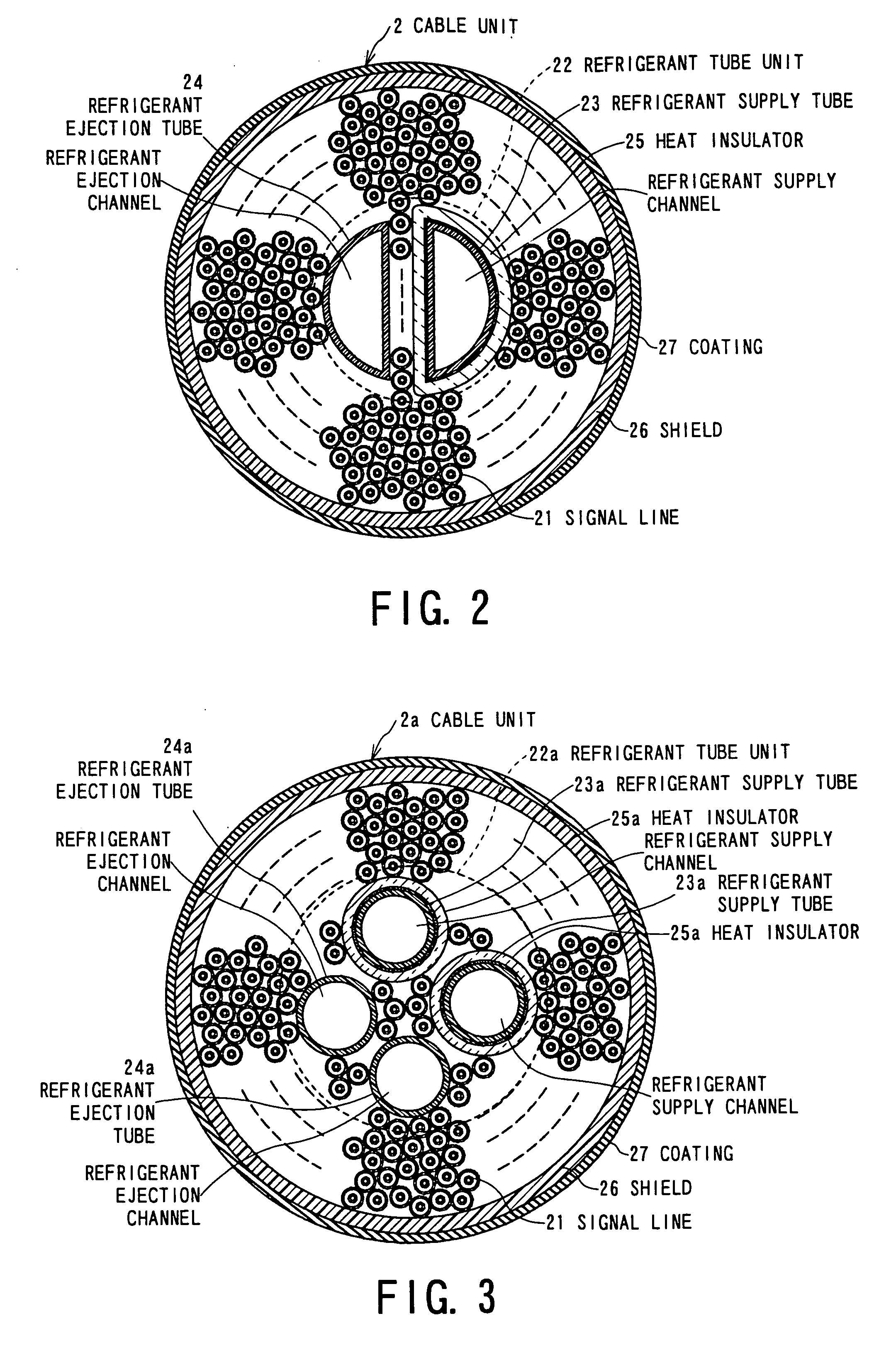
[0096]FIG. 4 is a sectional view showing a cable unit of an ultrasonic probe according to the second embodiment of the present invention. The point of an ultrasonic probe according to a second embodiment shown in FIG. 4 differing from the ultrasonic probe according to the first embodiment shown in FIG. 2 is that instead of the refrigerant tube unit, a multi-channel tube having four independent channels is provided in the longitudinal direction.

[0097] The cross-section of a cable unit 2b is circular, and in the vicinity of the center of the section, a multi-channel tube 22b having a circular cross-section is arranged. The multi-channel tube 22b is made of a flexible and heat insulating material such as silicone rubber or a soft vinyl chloride resin, and has two refrigerant supply channels 22b1 and two...

third embodiment

3. Third Embodiment

[0101] An ultrasonic probe according to a third embodiment of the present invention will be described below with reference to FIG. 5.

[0102]FIG. 5 is a sectional view showing a cable unit of an ultrasonic probe according to the third embodiment of the present invention. The point of an ultrasonic probe according to a third embodiment shown in FIG. 5 differing from the ultrasonic probe according to the first embodiment shown in FIG. 2 is that refrigerant ejection tubes are arranged away from center of a cable unit.

[0103] A cable unit 2c has a circular section. A refrigerant supply tube 23c is arranged on a portion in the vicinity of center inside the cable unit 2c. Signal lines 21 are arranged around the refrigerant supply tube 23c. A shield 26 is arranged around the signal lines 21 for shielding them. A coating 27 coats the shield 26 for insulating and protection.

[0104] Three refrigerant ejection tubes 24c are arranged on a circle, which is located within portio...


PUM


Abstract

An ultrasonic probe comprises a transducer part, a heat-receiving part, a refrigeration unit and a cable unit. The cable unit includes a signal line, a refrigerant supply tube, a refrigerant ejection tube and a heat insulator. The heat-receiving part absorbs heat generated from the transducer part. The refrigerant supply tube supplies a refrigerant from the refrigeration unit to the heat-receiving part. The refrigerant ejection tube sends the refrigerant for ejecting heat of the heat-receiving part to the refrigeration unit. The heat insulator is arranged around the refrigerant supply tube. A set of the refrigerant supply tube, the refrigerant ejection tube and the heat insulator is arranged at a center of the cable unit substantially while the signal line is arranged around at least one of the refrigerant supply tube, the refrigerant ejection tube and the heat insulator.

Description

BACKGROUND OF THE INVENTION [0001] 1. Field of the Invention [0002] The present invention relates to an ultrasonic probe and an ultrasonic diagnostic apparatus, and more particularly, to an ultrasonic probe and an ultrasonic diagnostic apparatus having a cooling system. [0003] 2. Description of the Related Art [0004] An ultrasonic diagnostic apparatus for examining an object by transmitting ultrasonic waves to the object so as to use the reflected waves has been widely used in a medical field. An ultrasonic probe for transmitting / receiving ultrasonic waves is used by bringing its leading end in contact with the object, and the ultrasonic probe includes a plurality of transducers which generate ultrasonic waves while converting received ultrasonic waves into electric signals. [0005] During operation of the ultrasonic diagnostic apparatus, not all the ultrasonic waves generated in the ultrasonic probe transmitting ultrasonic waves are transmitted to the object and part of them is abso...

Claims


Application Information

Patent Timeline
IPC IPC(8): A61B8/00
CPCA61B8/00A61B8/4455A61B8/546G10K11/004
Inventor HASHIMOTO, SHINICHI
Owner TOSHIBA MEDICAL SYST CORP
Why Eureka
Try Eureka