Diesel particulate filter using micro-wave regeneraiton

a technology of micro-wave regeneration and diesel particulate filter, which is applied in the direction of auxillary pretreatment, electrical control of exhaust treatment, separation process, etc., can solve the problems of low uniformity, low uniformity, and high risk of target hot sports and cold spots, etc., to achieve greater uniformity

Active Publication Date: 2006-05-18
GM GLOBAL TECH OPERATIONS LLC
View PDF8 Cites 23 Cited by
  • Summary
  • Abstract
  • Description
  • Claims
  • Application Information

AI Technical Summary

Benefits of technology

[0005] The present invention provides advantages and alternatives over the known art by providing a diesel particulate filter including a microwave-absorbing target at a defined position disposed within a waveguide cavity adapted to accept microwave-frequency electromagnetic radiation through input couplers 90 degrees out of phase with each other to excite circular polarization (CP) heating modes. Through excitation of CP modes, mode patterns are time-averaged azimuthally to smooth out the hot and cold spots in the heating pattern, thereby providing greater uniformity relative to corresponding linearly polarized modes. Still further uniformity may be realized by exciting combinations of CP modes so as to eliminate radial cold rings from the heating profile. It is contemplated that the microwave-absorbing target material is preferably embedded at or near the inlet end of the diesel particulate filter although other positions along the length of the filter may also be utilized if desired. The heating of the microwave absorbing media causes the particulate buildup to be vaporized and removed from the filter by the exhaust stream flow.

Problems solved by technology

Particulate buildup which is allowed to continue causes the filter to become clogged thereby giving rise to an undesirable increased pressure differential across the filter and leading to back pressure that reduces the engine efficiency.
However, a challenge in using microwave-frequency radiation is the achievement of uniform temperature distributions across a target material.
In particular, the use of microwave-frequency radiation in linearly polarized modes is highly susceptible to the creation of target hot sports and cold spots.
As explained above, such nonuniformity is generally inconsistent with the requirements for particulate filter regeneration.
Moreover, the environment of a particulate filter in a diesel exhaust system provides challenges with regard to space availability and cost constraints.
Suitable systems for diesel exhaust filter regeneration based on microwave heating are not believed to have been previously available.

Method used


Image

  • Diesel particulate filter using micro-wave regeneraiton
  • Diesel particulate filter using micro-wave regeneraiton
  • Diesel particulate filter using micro-wave regeneraiton

Examples


Embodiment Construction

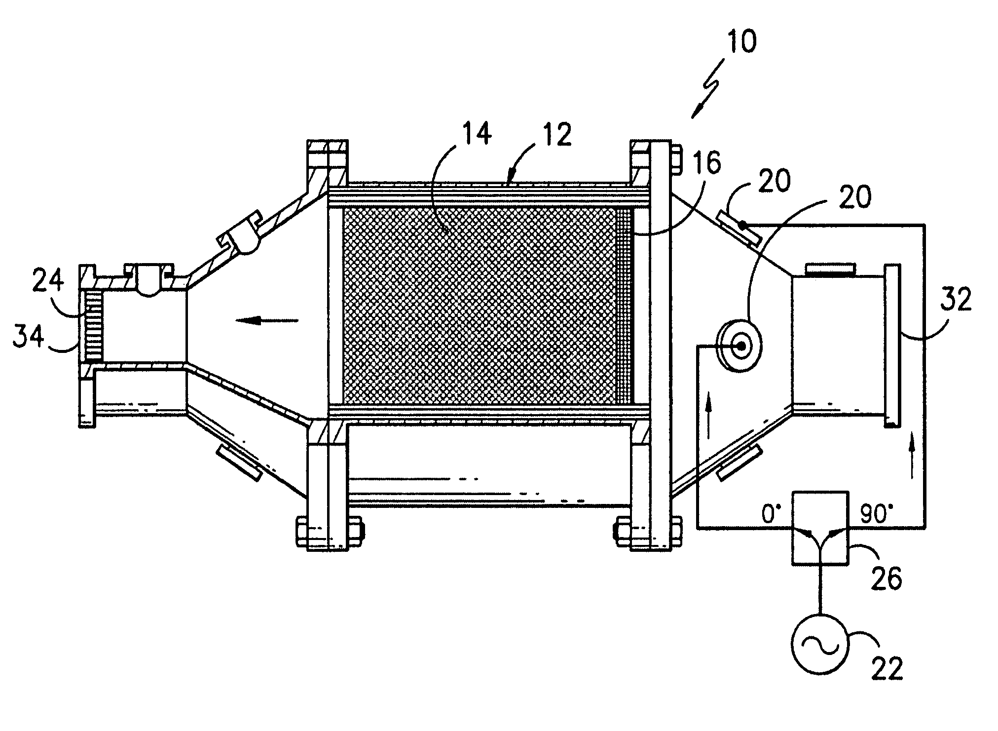
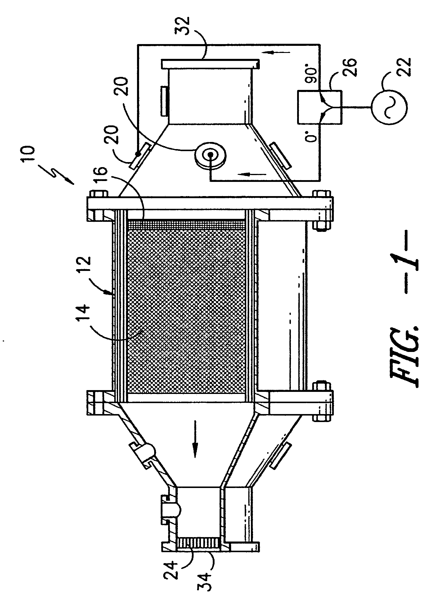
[0019] Reference will now be made to the various drawings wherein to the extent possible like elements are designated by corresponding reference numerals in the various views. In FIG. 1, there is illustrated a diesel particulate filter assembly 10 for disposition along the exhaust gas flow path down stream from a diesel engine (not shown). The direction of gas flow is illustrated by the directional arrow within the figure. According to the illustrated construction, the diesel particulate filter includes a cavity portion 12 that serves to contain a porous ceramic filter 14 and microwave-absorbing material 16 disposed in embedded contacting relation substantially across the cross-section of the filter 14. The cavity portion 12 may be formed of suitable materials such as metal and the like. In such a construction utilizing a metal cavity the interior walls surrounding the filter 14 may be conductive. The microwave-absorbing material 16 may be any one or a combination of well known subs...


PUM

PropertyMeasurementUnit
poweraaaaaaaaaa
temperatureaaaaaaaaaa
conductiveaaaaaaaaaa

Abstract

A diesel particulate filter including a microwave-absorbing target within a waveguide cavity. The cavity accepts microwave-frequency electromagnetic radiation through input couplers 90 degrees out of phase with each other to excite circular polarization heating modes. Through excitation of circularly polarized modes, heating patterns are time-averaged azimuthally to smooth out the hot and cold spots, thereby providing greater uniformity relative to heating patterns for corresponding linearly polarized modes.

Description

TECHNICAL FIELD [0001] The present invention relates generally to diesel particulate filter systems, and more particularly to a diesel particulate filter system utilizing a ceramic filter to trap particulate exhaust in combination with a localized target of microwave absorbing media positioned in close proximity to regions of particulate buildup within the ceramic filter such that heating the target causes the particulate build-up to undergo combustion and vaporization so as to clean the filter. The cavity housing the ceramic filter and microwave absorbing media is adapted to accept inputs of microwave-frequency electromagnetic radiation through input couplers excited 90 degrees out of phase with each other to reduce radial non-uniformity in heating patterns across the target so as to promote uniform particulate removal across the filter. BACKGROUND OF THE INVENTION [0002] The use of ceramic filters to entrap particulates carried by a diesel engine exhaust flow is known. In operatio...

Claims


Application Information

Patent Timeline
Patent Type & Authority Applications(United States)
IPC IPC(8): B01D46/00
CPCB01D53/944B01D2258/012B01D2259/806F01N3/0222F01N3/028F01N9/002F01N2330/02F01N2330/06Y02T10/47Y10S55/30Y10S55/10Y02T10/40
Inventor GREGOIRE, DANIEL J.COLBURN, JOSEPH S.
Owner GM GLOBAL TECH OPERATIONS LLC
Why Eureka
Try Eureka