Gas turbine engine system

Inactive Publication Date: 2006-05-18
NEWTON PROPULSION TECH
View PDF30 Cites 13 Cited by
  • Summary
  • Abstract
  • Description
  • Claims
  • Application Information

AI Technical Summary

Benefits of technology

[0009] It is an additional advantage of the present invention to provide a combustion engine system that can efficiently burn a broad range of fuels.
[0010] It is another object of the present invention to provide a combustion engine system that is cost effective.
[0011] It is a further object of the present invention to provide a gas turbine engine that overcomes the disadvantages of the prior art devices while retaining their inherent advantages.
[0012] It is a still furt

Problems solved by technology

A gas turbine engine is capable of rapid start-up and loading, and is likely to have a long life.
No effective cooling is possible.
However, the efficiency is reduced when the load is lowered, such as by lowering the operation temperature or the rotational velocity of the shaft.
Consequently, prior art gas turbine engines have

Method used


Image

  • Gas turbine engine system
  • Gas turbine engine system
  • Gas turbine engine system

Examples


Embodiment Construction

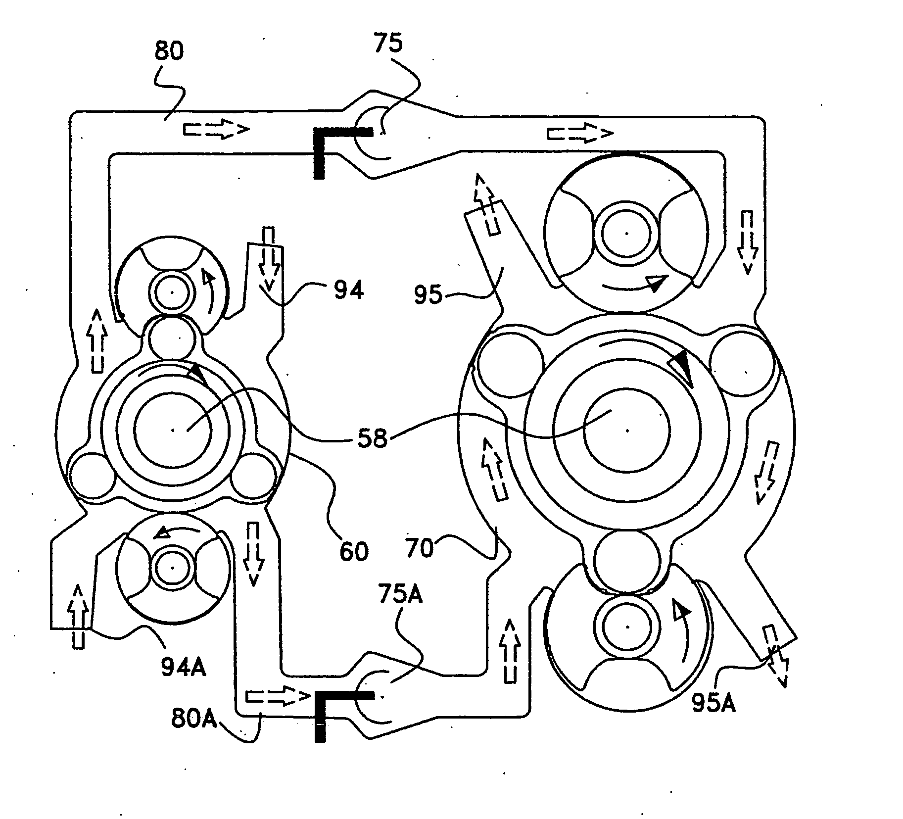
[0065] In one embodiment thereof, the present invention provides a novel gas turbine engine system in which the working fluid imparts a torque upstream to the turbine blades, so that a wide variation in load and shaft speed may be realized without a significant reduction in cyclical efficiency. Prior art gas turbine engines achieve a relatively high cyclical efficiency at full load when the kinetic energy of combustion gases flowing from a combustor to a turbine is at a maximum; however, their efficiency is significantly lowered following a reduction in kinetic energy of the combustion gases and a concomitant reduction in shaft speed. Use of prior art gas turbine engines is therefore precluded for those applications which require a wide variation in speed and load, such as land transportation or light aircraft. In contrast, the engine system of the present invention incorporates a positive displacement cycle by which a transfer volumetric device and an expansion volumetric device in...


PUM


Abstract

An engine system comprises at least a first volumetric device, and a second volumetric device in which said second volumetric device is larger in volume than said first volumetric device, in which, during continuous flow of a compressible fluid from said first to said second volumetric device work is performed.

Description

FIELD OF THE INVENTION [0001] The present invention relates to the field of thermal engine systems, particularly gas turbines. More particularly the invention relates to a gas turbine in which a controlled volume of fluid undergoes a continuous-flow positive displacement cycle. BACKGROUND OF THE INVENTION [0002] The vast majority of world-wide prime mover capacity is in the form of internal combustion engines. These include engines in automobiles, trucks, tractors, ships, airplanes, and stationary plants. Thermodynamically, engines are classified according to their basic cycle. With respect to reciprocating and other types of volumetric internal combustion engines. [0003] A volumetric internal combustion engine possesses an advantage over a conventional gas turbine engine in that it operates by means of static pressure within a closed volume which enables effective and efficient operation with low dependence on engine velocity and therefore relatively high efficiency and output thro...

Claims


Application Information

Patent Timeline
IPC IPC(8): F02G1/00F01B1/02F01B1/12F01B21/00F01C1/14F01C11/00F02B33/22F02B33/34F02B37/007F02B37/04F02B37/16F02B41/10F02B53/00F02B53/14F02C3/055F02C3/10F02C6/20F02K5/00
CPCF01C1/20F01C1/22F01C11/004F01C11/008F02B41/10F02B53/00F02B53/14F02B2053/005F02C3/055F02G1/02F02G2250/03F02K5/00F03C2/08Y02T10/163Y02T10/17Y02T10/12
Inventor ROM, HAIM
Owner NEWTON PROPULSION TECH
Why Eureka
Try Eureka